
The Global Terminology Trap: Two-Way vs. Three-Way
Before pulling any 14/3 NM-B or 3-core and earth cable, we must address a critical regional terminology discrepancy that causes countless wiring errors and safety hazards. In North America, the National Fire Protection Association (NFPA) and the National Electrical Code (NEC) define a setup where two separate switches control a single light load as a 3-way switch circuit. However, in the UK, Australia, and regions following IEC standards (such as BS 7671), this exact same configuration is universally called a 2-way switch circuit.
When DIYers and apprentices search for a wiring diagram for two way light switch configurations, they are almost always looking for the staircase, hallway, or large bedroom scenario: two separate physical switch locations controlling one overhead load. This guide uses the international '2-way' nomenclature while providing the exact North American '3-way' equivalents to ensure zero ambiguity, regardless of your local electrical code.
Expert Warning: Never confuse a UK '2-way' switch with a US '2-way' switch. In the US, a 2-way switch is a standard single-pole switch (one switch, one light). Using the wrong hardware or diagram for your region will result in a dead short or a continuously energized traveler wire.
Standard Wiring Diagram for Two Way Light Switch (Traveler Method)
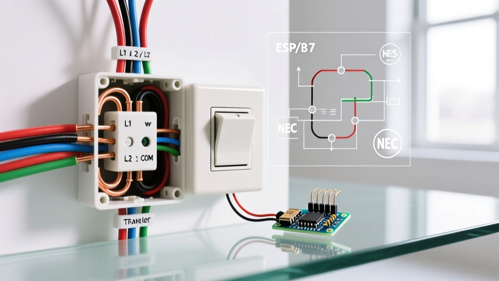
The most common and code-compliant method for wiring two switches to one light is the 'Traveler' (US) or 'Strapper' (UK) method. This requires a continuous connection between the two switch boxes using a 3-core cable, allowing the electrical current to be routed through alternating paths depending on the toggle position of each switch.
Component Breakdown & 2026 Material Costs
Material costs have stabilized in 2026, but sourcing the correct wire gauge and terminal-rated hardware is non-negotiable. Below is the specification matrix for a standard 15A / 10A lighting circuit.
| Component | US Spec (NEC) | UK/IEC Spec (BS 7671) | 2026 Est. Cost |
|---|---|---|---|
| Switch Hardware | Leviton Decora 5603 (15A) | Schneider Lisse 10A 2-Way | $8 - $14 |
| Interconnect Cable | 14/3 NM-B (Romex) w/ Ground | 1.5mm² 3-Core & Earth | $0.45 - $0.80 / ft |
| Wire Connectors | Ideal 341 Orange Wire-Nut | Wago 221-413 (3-Port Lever) | $12 / box of 50 |
| Testing Equipment | Fluke 117 True-RMS Multimeter | Fluke 117 True-RMS Multimeter | $215 |
Step-by-Step Execution: The Traveler Configuration
Follow this exact sequence to wire the circuit safely. Always verify the circuit is dead at the breaker and test with a non-contact voltage detector (NCVT) and a multimeter before touching any bare copper.
- Power to Switch 1 (Line): Route your main 14/2 (US) or 1.5mm² Twin & Earth (UK) supply cable into the first backbox. Connect the hot/live wire (Black or Brown) directly to the Common (COM) terminal. In US hardware, this is the distinctively colored black or dark brass screw.
- The Traveler Interconnect: Run your 14/3 or 3-Core & Earth cable between Switch 1 and Switch 2. Connect the Red and White (US) or Brown and Blue (UK) wires to the two brass traveler terminals (L1 and L2) on Switch 1. Connect the opposite ends to the L1 and L2 traveler terminals on Switch 2.
- Switch 2 to Load (Switched Hot): On Switch 2, connect the Common (COM) terminal to the black or brown wire of the 14/2 cable running up to the light fixture.
- Neutral Management: The neutral wires (White or Blue) bypass both switches entirely. They must be pigtailed together in the backboxes using Wago 221 connectors or wire nuts, continuing uninterrupted to the light fixture. Never switch the neutral wire.
- Grounding: Bond all bare copper ground wires to the green grounding screw on the switch yoke and the metal backbox (if applicable) using a grounding pigtail.
Edge Case: Bypassing 3-Core Cable with Smart Relays
In older homes, retrofitting a two-way switch setup is notoriously difficult because pulling new 14/3 or 3-core cable through finished walls and ceilings is destructive and expensive. The 2026 industry standard solution is utilizing a smart relay, such as the Shelly 1 or Lutron Caseta, paired with momentary switches.
- The Shelly 1 Method: This tiny relay sits behind the light fixture or in a deep junction box. It requires only a standard 14/2 (Live and Neutral) at the relay location. The two physical wall switches are replaced with momentary (push-button) switches. You only need a single standard traveler wire between the two switches to send a momentary pulse to the Shelly's SW terminal, toggling the relay state without requiring a dedicated 3-core strapper cable.
- Cost vs. Labor: A Shelly 1 relay costs approximately $22. While more expensive than a $9 mechanical switch, it saves hours of drywall repair and cable fishing, yielding a massive net-positive ROI on retrofits.
Troubleshooting: Ghost Voltages and Capacitive Coupling
A common failure mode in two-way switch circuits, particularly those with long cable runs exceeding 50 feet, is the presence of 'ghost voltages' on the traveler wires. If you test the travelers with a high-impedance digital multimeter (like the Fluke 117), you may read anywhere from 20V to 60V on the inactive traveler wire, even when the circuit is logically off.
The Cause: This is capacitive coupling. The energized traveler wire runs parallel to the unenergized traveler wire inside the same Romex or 3-core sheath. The electromagnetic field induces a phantom voltage in the adjacent wire.
The Fix: Do not assume the circuit is live and tear apart your connections. To verify if the voltage is real or a ghost, switch your multimeter to 'LoZ' (Low Impedance) mode, or use a solenoid voltage tester (wiggy). A LoZ test will drain the capacitive charge, dropping the ghost voltage to 0V, confirming the wiring is correct and safe.
2026 Code Compliance: AFCI and RCD Mandates
When installing or modifying a wiring diagram for two way light switch circuits, you must adhere to the latest protection mandates enforced by local inspectors.
- North America (NEC 2023/2026): Arc-Fault Circuit Interrupter (AFCI) protection is now strictly mandated for almost all 120V, 15A and 20A branch circuits supplying lighting outlets in living rooms, bedrooms, hallways, and closets. If you are upgrading a two-way switch in these areas, the breaker must be a Combination-Type AFCI. Standard breakers will fail inspection.
- UK / IEC (BS 7671 18th Edition): According to guidance from Electrical Safety First and the IET Wiring Regulations, all lighting circuits in domestic properties must be protected by a 30mA Residual Current Device (RCD) or RCBO. Ensure your consumer board is updated, as older lighting circuits were historically exempt from RCD protection prior to the 17th and 18th editions.
By understanding the exact terminal designations, respecting regional terminology, and applying modern troubleshooting techniques for capacitive coupling, you can confidently wire, upgrade, and repair two-way switch configurations to the highest professional standards.