
The Lethal Mistake: RV 30-Amp vs. Dryer 30-Amp Outlets
When homeowners decide to install an outdoor receptacle to power their travel trailer or motorhome, the most common and catastrophic error is confusing a 30-amp RV outlet with a 30-amp electric dryer outlet. While both are rated for 30 amps, their electrical architectures are entirely different. Understanding the correct wiring diagram for a 30 amp RV plug is not just a matter of code compliance; it is critical for preventing electrical fires and saving your RV’s onboard electronics from instant destruction.
An RV 30-amp plug utilizes a NEMA TT-30R configuration. This is a 120-volt, single-phase, 3-wire system. In stark contrast, older dryer outlets use a NEMA 10-30R (240V, no ground), and modern dryer outlets use a NEMA 14-30R (240V, with ground). If you wire a TT-30R receptacle using a 240V dryer circuit—or worse, use a cheater adapter to plug your RV into a dryer outlet—you will send 240 volts directly into your RV’s 120-volt neutral bus. This will instantly vaporize your RV's power converter, destroy sensitive microprocessors, and pose a severe electrocution hazard.
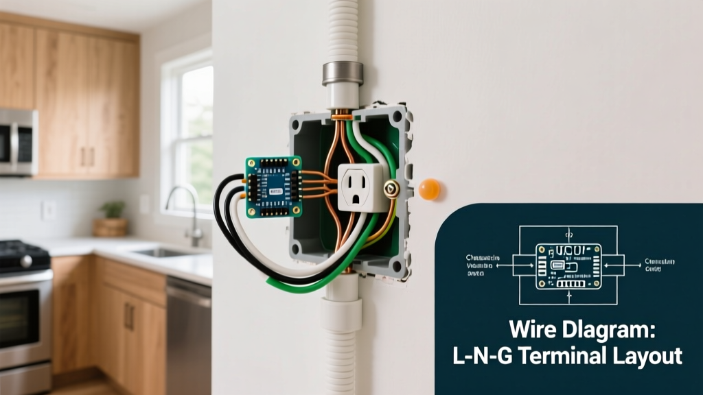
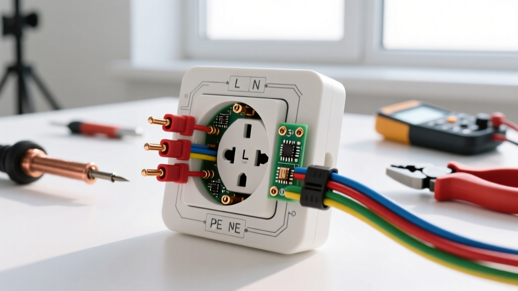
Official Wiring Diagram for a 30 Amp RV Plug (NEMA TT-30R)
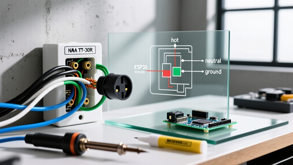
The NEMA TT-30R (Travel Trailer 30-Amp Receptacle) is uniquely designed to prevent accidental cross-plugging with 240V appliances. The face of the receptacle features three distinct slots: an angled hot blade, a horizontal neutral blade, and a U-shaped grounding pin.
Terminal Pinout Configuration
- X (Hot / Line): The angled blade. Connects to the 120V single-pole breaker via the BLACK wire.
- W (Neutral): The horizontal blade. Connects to the neutral bus bar via the WHITE wire.
- G (Ground): The U-shaped pin. Connects to the grounding bus bar via the BARE or GREEN wire.
Expert Note: Always verify the physical orientation of the TT-30R receptacle before terminating wires. The ground pin (U-shape) should be positioned at the bottom (6 o'clock position), the neutral (horizontal) at the top right, and the hot (angled) at the top left. Reversing the hot and neutral will cause reverse polarity, which will trip your RV’s internal surge protector and prevent power flow.
Material & Component Specifications
To ensure a safe, code-compliant installation that meets 2026 National Electrical Code (NEC) standards, you must select the correct materials. Undersized wire or incorrect breaker types are leading causes of voltage drop and thermal runaway at the pedestal.
| Component | Specification / Model | Purpose & Code Reference |
|---|---|---|
| Receptacle | Leviton 09300-RE or Hubbell 9300 | NEMA TT-30R, 125V, 30A. Specifically listed for RV use. |
| Circuit Breaker | 30-Amp Single-Pole GFCI | NEC 210.8(F) mandates GFCI protection for all outdoor receptacles up to 50A. |
| Wire (Conduit Run) | 10 AWG THWN-2 (Copper) | Minimum size for 30A. Must use 3 conductors (Black, White, Green/Bare). |
| Wire (Direct Burial) | 10/2 UF-B with Ground | For underground trenching without PVC conduit (minimum 12-inch burial depth). |
| Weatherproof Cover | Extra-duty while-in-use cover | NEC 406.9(B)(1) requires covers that accommodate the cord cap while plugged in. |
Step-by-Step Installation & Torque Specifications
Modern electrical codes strictly enforce terminal torque specifications to prevent loose connections, which cause arcing and fires. According to Leviton's official specifications, their 30-amp receptacles require precise torque on the terminal screws.
- Shut Off Power: Turn off the main breaker and verify zero voltage at the panel using a CAT-IV non-contact voltage tester and a digital multimeter.
- Install the GFCI Breaker: Snap the 30A single-pole GFCI breaker into your panel. Connect the white pigtail to the neutral bar, and the coiled white wire to the breaker's designated neutral terminal. Connect the black circuit wire to the breaker's hot terminal.
- Run the Cable: Pull your 10 AWG THWN-2 wires through a minimum 3/4-inch PVC conduit from the panel to the outdoor pedestal. If using 10/2 UF-B direct burial, ensure the trench is at least 12 inches deep and lay warning tape 6 inches above the cable.
- Strip and Terminate: Strip exactly 3/4 inch of insulation from the 10 AWG wires. Do not nick the copper.
- Apply Torque: Using a calibrated torque screwdriver (such as the CDI 401SM), tighten the terminal screws on the Leviton 09300-RE receptacle to 14 inch-pounds. This satisfies NEC 110.14(D) requirements. Over-torquing will strip the brass threads; under-torquing will cause high-resistance heating.
- Secure the Receptacle: Mount the TT-30R to the weatherproof box, ensuring the ground pin is at the bottom. Attach the extra-duty while-in-use cover.
Edge Case Troubleshooting: GFCI Nuisance Tripping & Voltage Drop
Even with a perfect wiring diagram for a 30 amp RV plug, DIYers frequently encounter two specific issues when plugging in their rigs for the first time.
1. The GFCI Nuisance Trip Phenomenon
Under current NFPA 70 (NEC) guidelines, outdoor RV receptacles must be GFCI protected. However, standard GFCI breakers trip at a 5-milliamp (mA) leakage threshold. Older RVs (manufactured pre-2015) often feature aging absorption refrigerators, degraded water heater elements, or faulty onboard converters that naturally leak 3 to 6 mA of current to the chassis ground. When you plug in, the new GFCI breaker detects this cumulative leakage and instantly trips.
The Fix: Do not remove the GFCI breaker to bypass the trip—this is a severe code violation and safety hazard. Instead, isolate the RV's internal faults. Unplug all internal 120V appliances (fridge, water heater, microwave). Reset the GFCI. Plug appliances back in one by one until the breaker trips, identifying the faulty component that requires repair or replacement.
2. Voltage Drop on Long Conduit Runs
If your RV pedestal is located 75 feet from your main electrical panel, using the minimum 10 AWG wire will result in unacceptable voltage drop. According to Copper Development Association guidelines, a 30-amp load on 75 feet of 10 AWG copper wire yields a voltage drop of approximately 5.4 volts (roughly 4.5%). The NEC recommends a maximum 3% voltage drop on branch circuits to prevent damage to RV air conditioner compressors.
The Fix: For any run exceeding 50 feet, upsize your conductors to 8 AWG copper. You will need to use a larger terminal lug or pigtail the 8 AWG wire to a 10 AWG pigtail to fit the TT-30R receptacle terminals, as most 30A receptacles are not physically rated to accept 8 AWG wire directly under the terminal screw.
Frequently Asked Questions
Can I wire a 30-amp RV outlet using a double-pole 30A breaker?
No. A double-pole 30A breaker provides 240 volts by combining two 120V legs. A NEMA TT-30R requires a single-pole 30A breaker to provide exactly 120 volts. Using a double-pole breaker will destroy your RV's electrical system.
Do I need a GFCI if my RV already has an internal surge protector?
Yes. An internal RV surge protector (like an EMS system) guards against over-voltage, under-voltage, and reverse polarity, but it does not replace the life-saving ground-fault protection required by the NEC for outdoor, wet-location receptacles. The GFCI breaker protects the human user from shock; the RV's EMS protects the RV's electronics.
What is the correct torque for 10 AWG wire on a TT-30R?
Most manufacturers, including Leviton and Hubbell, specify 14 inch-pounds for #10 AWG copper wire on 30-amp terminal screws. Always verify the torque spec printed on the back of the specific receptacle model you purchase, as metallurgical updates can occasionally shift manufacturer requirements.