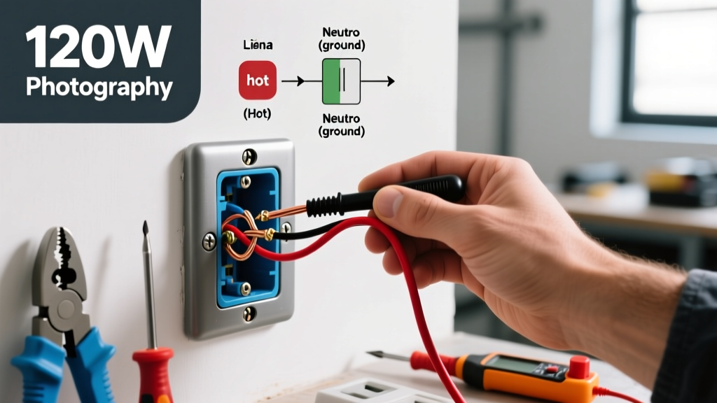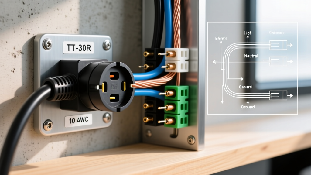

The Critical Danger: TT-30 vs. Dryer Outlets
Before pulling any wire, you must understand the most common and destructive mistake DIYers make when installing an RV pedestal: confusing a NEMA TT-30 (Travel Trailer 30-Amp) with a NEMA 10-30 or 14-30 (Electric Dryer) outlet. While both are rated for 30 amps, the NEMA TT-30 is strictly a 120-volt system, utilizing one hot, one neutral, and one ground. Dryer outlets are 240-volt systems. If you wire a TT-30 receptacle using a 240V dryer configuration, you will send 240 volts directly into your RV’s 120V appliances, instantly destroying your power converter, microwave, and electronics, while creating a severe fire hazard.
This guide provides the exact wiring diagram for 30 amp RV plug configurations (NEMA TT-30R receptacle and TT-30P plug), adhering to the 2026 National Electrical Code (NEC) Article 551 standards for recreational vehicle parks. Always consult the National Fire Protection Association (NFPA) for the latest NEC updates.
NEMA TT-30 Pinout and Wiring Diagram Matrix
Because visual schematics can sometimes be misinterpreted, below is a definitive structural matrix for the TT-30 wiring diagram. This applies to both the female receptacle (TT-30R) on your home pedestal and the male plug (TT-30P) on your RV power cord.
| Terminal Designation | Wire Color (NEC Standard) | Function | Voltage to Ground | Receptacle Screw Color |
|---|---|---|---|---|
| X | Black | Hot (Line 1) | 120V | Brass |
| W | White | Neutral | 0V (Ideally) | Silver |
| G | Bare Copper / Green | Equipment Ground | 0V | Green |
Expert Note: Unlike a 50-amp RV plug (NEMA 14-50) which utilizes X (Hot 1), Y (Hot 2), W (Neutral), and G (Ground), the 30-amp TT-30 completely omits the "Y" terminal. There is only one 120V hot leg.
Tools and Materials Required (2026 Pricing)
To execute this installation safely and up to code, you need specific materials. As of 2026, copper prices have stabilized, but buying quality components prevents premature failure.
- Circuit Breaker: 30A Single-Pole Breaker (e.g., Square D HOM130 or Eaton BR130). Cost: ~$9.00. Do NOT use a double-pole breaker with a handle tie.
- Wire: 10/2 NM-B (Romex) with ground for indoor/dry runs, or two strands of 10 AWG THHN (Black and White) plus 10 AWG green ground in PVC conduit for outdoor runs. Cost: ~$1.60 per foot.
- Receptacle: NEMA TT-30R (e.g., Leviton 303-PM or Hubbell 9430). Cost: ~$18.00 - $25.00. Avoid unbranded imports; they often lack proper internal thermal barriers.
- Torque Screwdriver: Calibrated to 14 in-lbs (e.g., CDI 1002MFRMHSS). Cost: ~$45.00. Mandatory for preventing thermal expansion loosening.
- Weatherproof Cover: Extra-duty while-in-use cover (e.g., TayMac MX1000S).
Step-by-Step Installation Guide
Step 1: Panel Preparation and Breaker Installation
Shut off the main breaker to your service panel. Verify the bus bars are dead using a non-contact voltage tester and a digital multimeter. Install the 30A single-pole breaker into an available slot. Connect the black (hot) wire to the breaker terminal, and torque it to the manufacturer’s specification (usually 35 in-lbs for Square D HOM series). Land the white (neutral) wire on the neutral bus bar and the bare copper ground on the grounding bus bar. Note: In a main service panel, neutral and ground are bonded; in a subpanel, they must remain strictly isolated.
Step 2: Routing and Sizing for Voltage Drop
The NEC requires 10 AWG copper for a 30-amp circuit. However, RV air conditioners draw heavy startup surges (up to 3,500 watts). If your outdoor pedestal is located more than 70 feet from the main panel, voltage drop becomes a critical factor. According to the RV Industry Association (RVIA) guidelines, operating an RV AC unit below 110V can burn out the compressor. For runs between 70 and 120 feet, upgrade your wire to 8 AWG copper to maintain a voltage drop of less than 3%. You can still terminate 8 AWG wire into a 30A breaker and TT-30R receptacle, though you may need to fold the bare wire carefully to fit the terminal clamps.
Step 3: Wiring the TT-30R Receptacle
Strip 3/4 inch of insulation from the black, white, and ground wires. Following the wiring diagram for 30 amp RV plug configurations:
- Ground (G): Connect the bare copper wire to the green terminal screw at the bottom of the receptacle.
- Neutral (W): Connect the white wire to the silver terminal screw on the right side (facing the front of the receptacle).
- Hot (X): Connect the black wire to the brass terminal screw on the left side.
Critical Torque Step: Use your torque screwdriver set to 14 in-lbs to tighten the terminal screws. Hand-tightening is the leading cause of melted RV plugs; a loose connection creates high resistance, generating enough heat to melt the plastic faceplate and cause a fire.
Step 4: Mounting and Weatherproofing
Secure the receptacle to the weatherproof box using the provided stainless steel screws. Attach the extra-duty "while-in-use" cover. This cover allows the RV plug to remain inserted while keeping the seal closed against rain and snow, a strict requirement for outdoor 120V receptacles per NEC Article 406.9.
Step 5: Multimeter Verification Testing
Before plugging in your RV, turn the main panel back on and flip the new 30A breaker to the ON position. Set your digital multimeter to AC Voltage (V~) and perform the following tests at the receptacle:
- Hot to Neutral (X to W): Should read 118V - 124V.
- Hot to Ground (X to G): Should read 118V - 124V.
- Neutral to Ground (W to G): Should read 0V to 1.5V (anything higher indicates a floating or loose neutral upstream).
If you read 240V between X and W, stop immediately. You have wired it to a double-pole 240V breaker. Correct this before proceeding. For more on workplace and residential electrical testing safety, refer to OSHA Electrical Safety Guidelines.
Common Failure Modes and Troubleshooting
Even with a perfect wiring diagram for 30 amp RV plug setups, environmental and mechanical factors can cause failures over time.
1. Melted Plug Prongs (Thermal Runaway)
The Problem: The brass prong on the RV’s male plug becomes discolored, warped, or melts into the receptacle.
The Cause: This is rarely a wire sizing issue. It is almost always caused by undersized terminal torque at the receptacle or corrosion on the male plug blades. As the AC compressor cycles on, it pulls 15-20 amps. A loose screw creates a micro-arc, generating localized heat exceeding 400°F.
The Fix: Replace both the male TT-30P plug and the female TT-30R receptacle. Clean the new plug blades with fine-grit sandpaper and apply a thin coat of dielectric grease to prevent oxidation.
2. RV Converter Humming and Flickering Lights
The Problem: When plugged into the new pedestal, the RV’s internal lights flicker, and the power converter emits a loud buzzing sound.
The Cause: Severe voltage drop. The wire run is too long for 10 AWG, or there is a corroded connection at the panel bus bar.
The Fix: Measure the voltage at the pedestal under load (with the RV AC running). If it drops below 112V, you must either upgrade the wire run to 8 AWG or install a dedicated RV auto-transformer voltage booster inside the RV.
Frequently Asked Questions
Can I use a 50-amp breaker and wire, but just install a 30-amp TT-30 receptacle?
No. The NEC strictly prohibits over-fusing a receptacle. A NEMA TT-30R is rated for a maximum 30-amp overcurrent protection device. If you use a 50-amp breaker, the receptacle could melt and catch fire before the breaker ever trips during a short circuit. The breaker must match the lowest rated component in the circuit, which is the 30A receptacle.
Is it legal to install a TT-30 receptacle indoors in my garage?
Yes, you can install a TT-30R indoors to power an RV stored in a garage or barn. However, it must be on a dedicated circuit. You cannot share the neutral or ground with other garage outlets, and it must be protected by a GFCI breaker if local 2026 NEC amendments require GFCI protection for all 125V/250V receptacles in garages and outbuildings (NEC 210.8).
My RV has a 30-amp plug, but my house only has a 50-amp 240V dryer outlet. Can I use an adapter?
You can use a certified "Dogbone" adapter (NEMA 14-30P to TT-30R or 10-30P to TT-30R) only if the adapter contains an internal step-down transformer or if you are absolutely certain the dryer outlet was wired specifically as a 120V dedicated circuit (which is incredibly rare and non-standard). Standard adapters simply reconfigure the pins. Plugging a 120V RV into a true 240V dryer outlet via a passive adapter will destroy your RV. Always verify the voltage of the source outlet with a multimeter before using any adapter.