
The Regulatory Framework: Governing the Type G Electrical Outlet
The Type G electrical outlet, universally recognized as the British standard plug and socket system, is governed by some of the most rigorous electrical safety codes in the world. Unlike North American NEMA standards or European Schuko systems, the Type G system incorporates a unique philosophy: point-of-use fusing and mechanical shutter interlocks. For electricians, engineers, and DIY enthusiasts working in the UK, Ireland, Malta, Malaysia, Singapore, and various other territories, understanding the code requirements for a Type G electrical outlet is non-negotiable.
Two primary documents dictate the manufacturing and installation of these devices:
- BS 1363: The product standard specifying the physical dimensions, thermal limits, and mechanical safety features of the plugs and socket-outlets themselves.
- BS 7671 (The IET Wiring Regulations): The installation code (currently the 18th Edition) that dictates how Type G outlets must be wired, protected, and tested within a building's electrical infrastructure.
According to the The Plugs and Sockets etc. (Safety) Regulations 1994, it is a criminal offense in the UK to supply or install socket-outlets that do not comply with the relevant safety provisions of BS 1363. This ensures that every Type G electrical outlet installed in a modern property meets strict thermal and mechanical benchmarks.
Circuit Topologies: Ring Final vs. Radial Wiring
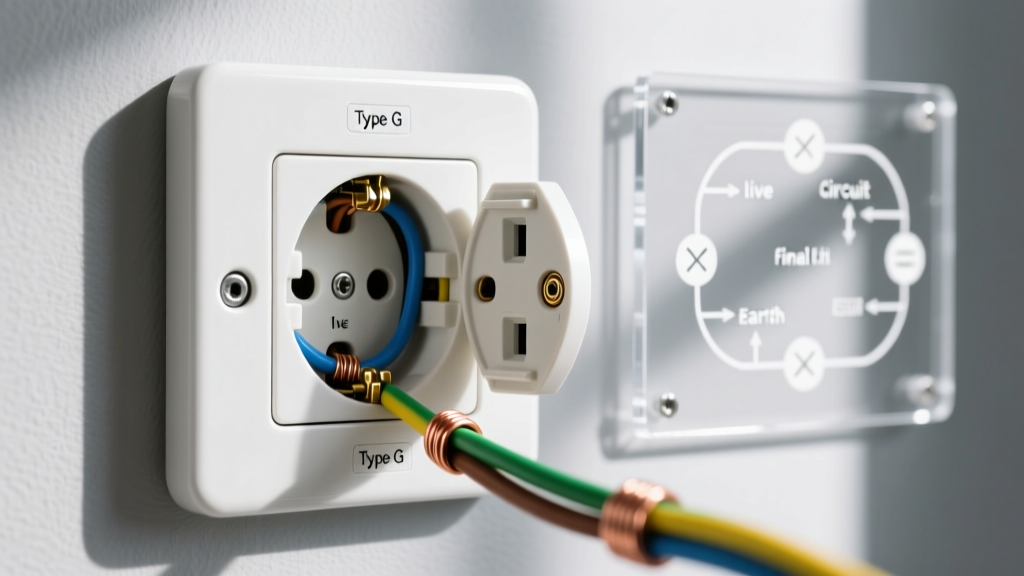
One of the most defining code requirements for Type G outlets in the UK is the permitted circuit topology. While radial circuits are standard globally, BS 7671 uniquely permits and heavily regulates the Ring Final Circuit (RFC) for socket-outlets.
Comparing Ring Final and Radial Circuit Parameters
| Parameter | Ring Final Circuit (RFC) | Radial Circuit (Standard) |
|---|---|---|
| Overcurrent Protection (MCB) | 32A (Type B or C) | 16A, 20A, or 32A |
| Minimum Cable Size (Cu) | 2.5mm² (PVC insulated) | 2.5mm² (16A/20A) or 4.0mm² (32A) |
| Maximum Floor Area Served | 100m² per ring | 50m² (20A) or 75m² (32A) |
| Spur Limitations | Unlimited spurs if protected by 13A fuse; otherwise max 1 single/double socket per unfused spur | No spurs permitted on 4.0mm²; standard branching allowed on radials with appropriate MCB sizing |
Note: When installing a Type G electrical outlet on an RFC, the continuity of the ring must be verified. A break in the ring turns the circuit into two unprotected radial legs, potentially overloading the 2.5mm² cable if the 32A MCB does not trip in time.
Mechanical Code Requirements: Shutters and Pin Dimensions
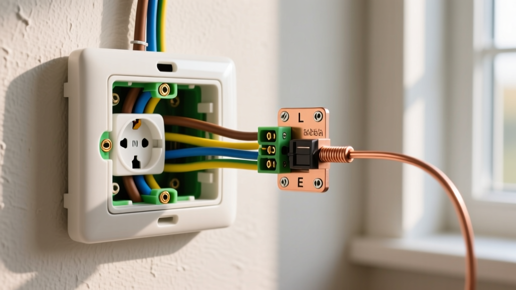
The physical design of the Type G outlet is heavily regulated to prevent accidental contact with live parts. BS 1363 mandates an interlocking shutter mechanism. The shutters covering the Line (L) and Neutral (N) apertures cannot be opened independently; they are mechanically released only when the longer Earth (E) pin is inserted.
For a Type G electrical outlet to pass BS 1363 compliance, the internal dimensions and pin clearances must adhere to strict tolerances:
- Earth Pin Length: Must be between 22.23mm and 23.80mm. This ensures the earth connection is made, and the shutters are opened, before the L/N pins make electrical contact.
- Line/Neutral Pin Length: Must be between 17.2mm and 18.6mm.
- Insulation Sleeving: The L and N pins must have an insulated sleeve covering the base (approx. 9mm), ensuring that if a plug is partially pulled out, a user cannot touch a live metal pin.
Expert Warning: Never bypass or tape over the Earth pin on a Type G plug to force the shutters open. As highlighted by Electrical Safety First, using foreign objects or damaged plugs to defeat the shutter mechanism is a leading cause of severe arc flashes and fatal shocks in domestic environments.
Modern Integrations: USB-Equipped Type G Sockets
With the proliferation of smart devices, USB-integrated Type G outlets have become standard. However, these are not treated as simple mechanical pass-throughs. They must comply with BS 1363-4, which covers socket-outlets with incorporated USB chargers.
Thermal and Isolation Requirements for USB Outlets
When installing or specifying USB Type G outlets (such as the MK Logic Plus USB or Crabtree Evolve ranges), electricians must be aware of the following code-mandated limits:
- Galvanic Isolation: The USB charging circuitry must be safely isolated from the 230V AC mains. The internal transformer must meet EN 61558-2-16 standards for switch-mode power supplies.
- Temperature Rise: Under full continuous load (e.g., charging two tablets simultaneously at 2.1A or 3.0A each), the external surface temperature of the socket faceplate must not exceed 40°C above ambient room temperature. This prevents thermal degradation of the PVC faceplate and the wall backing box.
- Creepage and Clearance: Internal PCB spacing between the 230V AC primary side and the 5V DC secondary side must maintain a minimum creepage distance of 6.4mm to prevent internal arcing.
Pro Installation Specs: Torque and Termination
A frequent point of failure in Type G outlet installations is improper termination. BS 7671 Regulation 526.6 requires that all electrical connections be made with the appropriate force to ensure lasting mechanical and electrical integrity without damaging the conductor.
- Stripping Length: Standard 13A socket-outlets (like the BG Nexus or Schneider Lisse ranges) require a strip length of exactly 12mm to 14mm. Exposing too much bare copper creates a shock hazard at the terminal entry; too little results in the terminal screw biting into the PVC insulation, causing a high-resistance joint and eventual thermal failure.
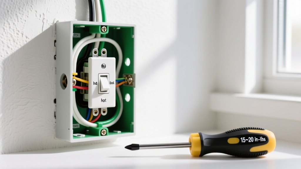
- Terminal Torque: While many domestic electricians rely on 'hand-tight' estimates, commercial and high-spec residential installations require a calibrated torque screwdriver. For standard brass terminals on a 13A Type G outlet, the manufacturer-specified torque is typically between 1.2 Nm and 1.5 Nm. Over-torquing can shear the terminal screw or crush stranded conductors, while under-torquing leads to loose connections and localized heating.
- Earth Sleeving: The Circuit Protective Conductor (CPC) must be sleeved with green/yellow PVC tubing right up to the terminal. Bare earth wires inside the backbox are a code violation.
Mandatory Testing and Commissioning
Once the Type G electrical outlet is wired, BS 7671 Chapter 64 mandates rigorous testing before the circuit is energized. Relying solely on visual inspection is a code violation.
Key Testing Parameters for Socket-Outlet Circuits
- Continuity of Protective Conductors (R1 + R2): For a Ring Final Circuit, the end-to-end resistance of the Line, Neutral, and Earth loops must be measured. The Earth loop resistance (r2) is typically 1.67 times higher than the Line loop (r1) due to the smaller cross-sectional area of the CPC in standard 2.5mm²/1.5mm² twin and earth cable.
- Earth Fault Loop Impedance (Zs): The measured Zs at the furthest Type G outlet on the circuit must not exceed the maximum permissible values listed in BS 7671 Chapter 41. For a 32A Type B MCB, the maximum Zs is 1.37 Ω (at 10°C correction). If the reading is higher, the MCB may not trip fast enough during a fault.
- RCD Trip Times: If the Type G outlets are protected by an RCD or RCBO (mandatory for most domestic socket circuits under the 18th Edition), it must trip within 40 milliseconds at 5x IΔn (e.g., 150mA for a 30mA device) and within 300 milliseconds at 1x IΔn (30mA).
For comprehensive testing methodologies and updates to the wiring regulations, professionals should regularly consult the IET BS 7671 Wiring Regulations portal.
Frequently Asked Questions (FAQ)
Can I install a Type G outlet on a 16A radial circuit using 2.5mm² cable?
Yes. BS 7671 permits 2.5mm² copper cable on a 16A Type B MCB radial circuit. This is common in modern apartment builds or specific kitchen appliance loops. However, you cannot use 2.5mm² cable on a 20A or 32A radial circuit without applying specific installation method derating factors.
Are switchless Type G outlets permitted in domestic properties?
Yes, unswitched Type G outlets are perfectly legal and code-compliant. However, switched outlets (where a local rocker switch isolates the Line conductor) are heavily preferred in the UK for convenience and safety, allowing users to kill power to an appliance without unplugging it. Switched outlets must feature a clear 'ON/OFF' indicator and a minimum contact gap of 3mm.
Do Type G outlets require deep backboxes?
While standard 25mm backboxes are technically permissible, BS 7671 and best practice guidelines strongly recommend using 35mm deep backboxes (or deeper). This provides adequate volume for the mandatory bending radii of 2.5mm² cables, prevents insulation damage from being crushed against the plaster, and allows space for smart home modules or WAGO connectors if spurring.