
Introduction to Receptacle Diagnostics
When a standard 15-amp or 20-amp duplex receptacle stops delivering power, the immediate assumption is often a tripped breaker or a blown fuse. However, as any seasoned electrician knows, the root cause of wiring electrical outlet failures usually lies hidden behind the faceplate. From degraded push-in connections to shared neutral faults and improper torque specifications, diagnosing a dead or underperforming outlet requires a systematic, measurement-based approach.
This comprehensive diagnostic guide moves beyond basic receptacle testers. We will explore advanced multimeter testing flows, analyze thermal failure modes in modern receptacles, and apply current National Electrical Code (NEC) standards to ensure your troubleshooting results in a safe, long-lasting repair.
Essential Diagnostic Toolkit for 2026
Before removing a single faceplate screw, you must equip yourself with the right diagnostic instruments. Relying solely on a basic three-light cube tester will leave you blind to high-resistance connections and voltage drop issues.
- True-RMS Digital Multimeter (DMM): The Fluke 117 Electricians True RMS Multimeter (approx. $199) or the Klein Tools MM400 (approx. $50) are industry standards. True-RMS is critical for accurately reading voltage on circuits with non-linear loads like LED drivers and switching power supplies.
- Non-Contact Voltage Tester (NCVT): The Klein Tools NCVT-3 ($35) offers dual-range sensitivity (12-1000V and 70-1000V), allowing you to verify the absence of voltage at the breaker panel before approaching the outlet.
- Torque Screwdriver: Modern electrical codes mandate precise terminal torque. A Wiha 1/4-inch torque screwdriver set to 14 lb-in (pound-inches) is required for most standard Leviton and Hubbell 15A/20A receptacles.
- SureTest Circuit Analyzer: Devices like the Amprobe INSP-3 go beyond basic polarity checks, measuring actual ground impedance and predicting whether a breaker will trip within the required timeframe.
The 'Dead Outlet' Diagnostic Flow
When troubleshooting wiring electrical outlet configurations that appear completely dead, follow this sequential isolation process to pinpoint the exact failure node.
Step 1: Panel Verification and NCVT Sweep
Locate the corresponding circuit breaker at the main panel. Turn it off, then use your NCVT to scan the receptacle slots. Warning: Always test the NCVT on a known live circuit first to verify the tool's battery and functionality. If the NCVT indicates voltage is still present, you have misidentified the breaker, or the circuit is backfed through a shared neutral or a multi-wire branch circuit (MWBC).
Step 2: Faceplate Removal and Visual Inspection
With the power confirmed off, remove the faceplate and extract the receptacle. Look for immediate visual cues:
- Discoloration or Melting: Brown or black scorch marks around the terminal screws indicate high-resistance arcing, usually caused by loose connections or aluminum wire oxidation.
- Backstabbed Wires: If 14 AWG or 12 AWG solid copper wires are pushed into the rear spring-loaded holes (backstabbed), you have found your probable culprit. (More on this failure mode below).
- Cracked Yoke: The mounting strap (yoke) can crack if over-tightened against an uneven drywall surface, compromising the internal brass bus bars.
Step 3: Live Voltage Testing (The Three-Point Check)
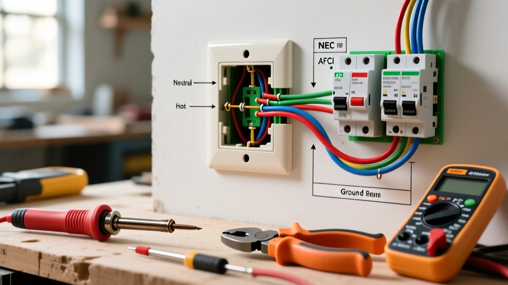
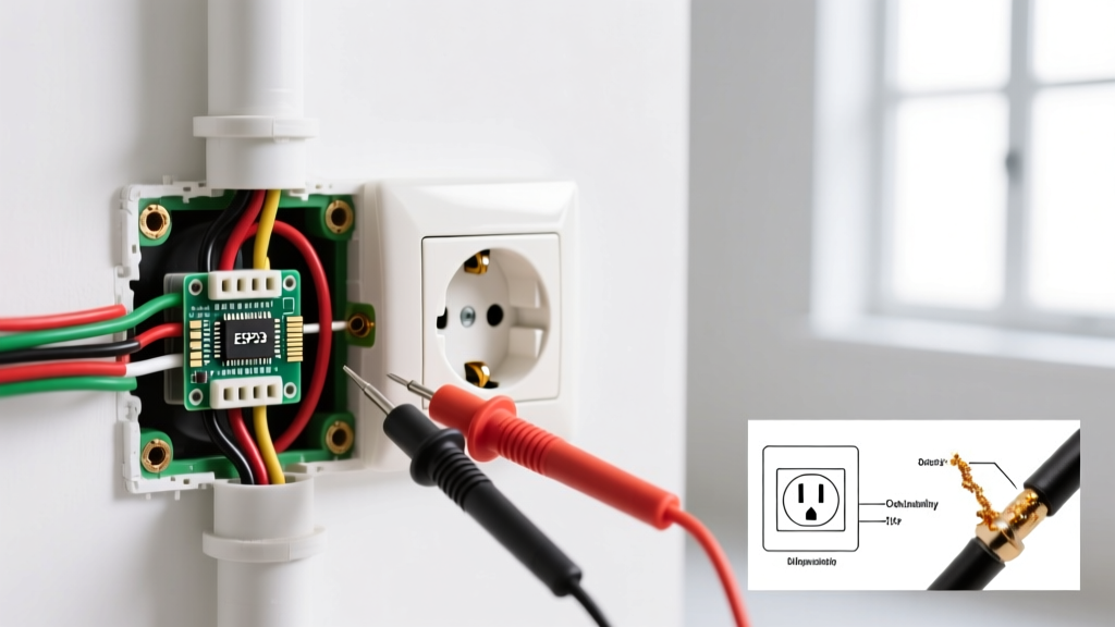
Restore power at the breaker. Using your True-RMS multimeter set to AC Voltage, perform the three-point test directly at the terminal screws (not the face slots, which can yield false readings due to worn internal contacts).
Expert Safety Note: Never perform live voltage testing on the terminal screws unless you are wearing appropriate PPE and using CAT III or CAT IV rated test leads. If you are uncomfortable with live testing, perform continuity and resistance testing with the power OFF.
Voltage Reading Diagnostic Matrix
Use the following matrix to interpret your three-point multimeter readings. A standard healthy branch circuit should read between 118V and 124V, depending on your local utility's transformer tap settings.
| Hot-to-Neutral | Hot-to-Ground | Neutral-to-Ground | Diagnostic Conclusion | Required Action |
|---|---|---|---|---|
| 120V | 120V | 0V - 2V | Normal / Healthy Circuit | None. Receptacle is wired correctly. |
| 120V | 0V | 0V | Open Ground | Check ground wire connection at the box and panel. Verify grounding electrode system. |
| 0V | 120V | 120V | Open Neutral | Trace the neutral (white) wire back to the previous device in the daisy chain. Look for failed backstab connections. |
| 120V | 120V | 110V+ | Hot-Neutral Reversed | Immediate shock hazard. Swap the black and white wires on the brass and silver terminals. |
| 90V - 110V | 90V - 110V | 0V | Severe Voltage Drop | Check for loose connections upstream, undersized wire for the run length, or corroded bus bars in the panel. |
The Silent Killer: Backstab vs. Screw Terminal Failures
When troubleshooting wiring electrical outlet setups in homes built between 1990 and 2015, the most common hidden failure is the 'backstabbed' connection. Receptacles feature rear-entry push-in holes that use a small internal brass spring to grip the stripped wire. While this saves installers time, it is a massive point of failure.
The Physics of Thermal Cycling
When a high-draw appliance (like a space heater drawing 12.5 amps or a window AC unit) is plugged in, the internal brass spring heats up and expands. When the appliance is turned off, the spring cools and contracts. Over 5 to 10 years of this thermal cycling, the spring loses its tension. The contact area between the wire and the spring shrinks, increasing electrical resistance.
According to Joule's First Law ($P = I^2R$), as resistance ($R$) increases at the junction, power ($P$) is dissipated as heat. This localized heat further degrades the spring, eventually leading to an open neutral or a localized melt-down that can ignite surrounding insulation. The U.S. Consumer Product Safety Commission (CPSC) regularly highlights loose connections as a primary catalyst for residential electrical fires.
The Permanent Fix
When diagnosing a dead outlet downstream of a backstabbed receptacle, always remove the backstabbed wires. Use the release slot to free the wire, strip it back to fresh copper, and terminate it using the side screw terminals. For 12 AWG wire, wrapping the wire clockwise around the screw ensures that tightening the screw pulls the loop tighter.
Advanced Code Compliance: Torque Specifications
A major shift in modern electrical safety is the enforcement of terminal torque specifications. Section 110.14(D) of the National Electrical Code (NEC) mandates that terminations must be tightened to the torque values specified by the manufacturer. Most electricians tighten screws 'until they feel snug,' which often results in over-torquing.
Over-torquing a 15A receptacle terminal (which typically requires 14 lb-in) can strip the brass screw head, crush the copper wire reducing its cross-sectional area, or crack the thermoplastic housing. Under-torquing leads to the exact thermal cycling failures described above. Investing in a calibrated torque screwdriver is no longer optional for professional-grade troubleshooting and repair.
GFCI and AFCI Nuisance Tripping Diagnostics
Sometimes the outlet isn't dead; it's being actively interrupted by upstream protection. If you are troubleshooting a GFCI (Ground Fault Circuit Interrupter) or AFCI (Arc Fault Circuit Interrupter) that refuses to reset:
- Downstream Ground Faults: A GFCI protects everything wired to its 'LOAD' terminals. If a downstream outdoor receptacle has moisture ingress, the GFCI will trip. Disconnect the LOAD wires at the GFCI. If it resets, the fault is downstream, not in the GFCI itself.
- AFCI Parallel Arcs: AFCI breakers look for the high-frequency signatures of arcing. A loose neutral wire anywhere on the branch circuit will create a parallel arc that the breaker detects. Tightening all neutral connections in the circuit's junction boxes usually resolves this.
- Shared Neutrals (MWBC): If a multi-wire branch circuit shares a neutral, and the two hot legs are on the same phase (due to a breaker installation error), the neutral will carry the sum of the currents rather than the difference, leading to overheating and AFCI/GFCI confusion.
Conclusion
Troubleshooting wiring electrical outlet failures requires moving past simple assumptions. By utilizing a True-RMS multimeter, understanding the three-point voltage matrix, and replacing outdated backstabbed connections with properly torqued screw terminations, you ensure the safety and longevity of the branch circuit. Always consult the latest NEC guidelines and prioritize measurement over guesswork when diagnosing electrical faults.