
The Myth of Exactly 120V
When homeowners, DIYers, and even some apprentice electricians refer to a standard receptacle, they almost universally call it a '120V outlet.' However, if you plug a high-quality digital multimeter into a standard electrical outlet, you will rarely see exactly 120.0 volts. The reality of power distribution is that utility companies deliver electricity across vast, complex grids subject to varying loads, transformer tap settings, and line losses. Understanding the true standard electrical outlet voltage is the first step in professional-grade electrical inspection and troubleshooting.
Measuring the voltage at your receptacles is not just an academic exercise; it is a critical diagnostic tool. Voltage that is too low can cause motors in appliances like refrigerators and HVAC systems to overheat and fail prematurely. Voltage that is too high can degrade the lifespan of sensitive electronics, LED drivers, and smart home hubs. In this comprehensive inspection guide, we will break down the exact tolerances, the tools required for precise measurement, and the step-by-step protocol for testing and diagnosing standard electrical outlet voltage in residential and light-commercial environments.
Decoding the ANSI C84.1 Voltage Standard
To determine if an outlet is operating correctly, you must know the legally and technically acceptable ranges. In North America, the definitive authority on voltage tolerances is the American National Standards Institute (ANSI), specifically the ANSI C84.1 standard for electric power systems and equipment.
ANSI C84.1 Range A (Optimal): The nominal 120V system should operate between 114V and 126V. Utility providers and facility managers must design systems to stay within this band for the majority of operating hours.
ANSI C84.1 Range B (Acceptable but Action Required): Voltages between 110V and 114V, or between 126V and 127V. These conditions can occur due to extreme grid loads or specific local transformer configurations. While equipment will generally function, continuous operation in Range B is not recommended and warrants investigation.
According to the U.S. Energy Information Administration (EIA), the evolution of the nominal voltage from 110V to 115V, and finally to the modern 120V standard, was driven by the need to deliver more power over existing wire gauges without increasing current. Therefore, when testing your standard electrical outlet voltage, any reading outside the 114V–126V window indicates a localized wiring issue, a failing utility transformer, or an overloaded circuit.
The 2026 Inspector's Toolkit
Accurate testing requires reliable equipment. Cheap, uncalibrated testers can give false readings, leading to unnecessary panic or missed hazards. Here is the recommended toolkit for serious DIYers and professional inspectors:
- Digital Multimeter (DMM): The Fluke 117 True RMS Multimeter (approx. $215) is the industry gold standard. Its True RMS capability ensures accurate AC voltage readings even if the sine wave is distorted by harmonic loads (like cheap LED drivers or variable frequency drives). For a budget alternative, the Klein Tools MM400 (approx. $45) offers solid reliability for basic residential testing.
- Receptacle Tester: The Klein Tools RT250 GFCI Receptacle Tester (approx. $38) features a digital LCD that displays the exact voltage alongside wiring fault indicators (open ground, reverse polarity). This allows for rapid, safe initial screening before breaking out the DMM.
- Non-Contact Voltage Tester (NCVT): Essential for initial safety verification. The Fluke 2AC VoltAlert (approx. $35) should be used to confirm the presence of voltage before and after testing.
- PPE: When probing live terminals, always wear ANSI-rated safety glasses and insulated gloves, adhering to guidelines established by OSHA's electrical safety standards.
Step-by-Step Multimeter Testing Protocol
Follow this precise sequence to measure standard electrical outlet voltage safely and accurately. Never rush this process; working on energized circuits carries inherent risks.
- Verify Your Meter: Before testing the target outlet, test your multimeter on a known-good circuit (like a dedicated appliance outlet) to ensure the battery is strong and the leads are intact.
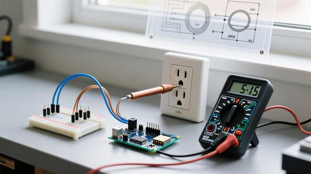
- Set the Dial: Turn the DMM dial to AC Voltage (V~ or VAC). Ensure the range is set to auto-ranging or manually set to a scale higher than 120V (e.g., 200V or 600V).
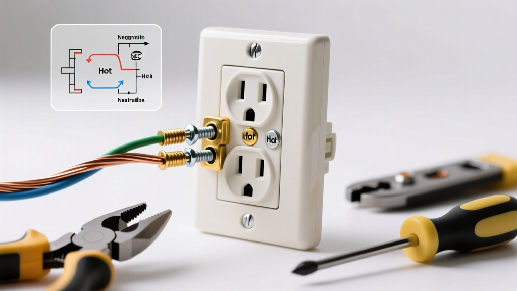
- Hot-to-Neutral Test (The Baseline): Insert the black (common) probe into the longer vertical slot (Neutral). Insert the red (hot) probe into the shorter vertical slot (Hot). Record the reading. This is your primary standard electrical outlet voltage.
- Hot-to-Ground Test (The Verification): Move the black probe to the round bottom hole (Ground). Keep the red probe in the Hot slot. The reading should be nearly identical to the Hot-to-Neutral reading (usually within 0.5V). If it is significantly higher, you have a loose or broken neutral connection.
- Neutral-to-Ground Test (The Fault Finder): Place the black probe in Neutral and the red probe in Ground. This reading should be very low—typically between 0.0V and 2.0V. A reading above 3V indicates excessive voltage drop on the neutral wire or an improperly bonded neutral-ground system.
Voltage Diagnostic Matrix
Use this structured matrix to interpret your multimeter readings and determine the appropriate corrective action. This framework aligns with troubleshooting methodologies outlined in the National Fire Protection Association's National Electrical Code (NEC).
| Hot-to-Neutral Reading | Neutral-to-Ground Reading | Probable Cause | Recommended Action |
|---|---|---|---|
| 114V - 126V | 0.0V - 2.0V | Normal Operation (ANSI Range A) | No action required. Circuit is healthy. |
| 105V - 113V | 0.5V - 5.0V | Severe Voltage Drop / Overloaded Circuit | Check wire gauge vs. breaker size. Reduce load or run a dedicated 12 AWG circuit. |
| 127V - 135V | 0.0V - 1.0V | Utility Transformer Tap Set Too High | Call utility provider to adjust transformer taps. Do not use surge suppressors as a permanent fix. |
| 60V - 90V | 30V - 60V | Phantom Voltage / Open Neutral / High Resistance | Inspect panel neutral bus bar. Check for backstabbed wires or loose wire nuts at the receptacle. |
| 0V | 0V | Tripped Breaker / Open Hot / GFCI Fault | Reset GFCI or breaker. Trace circuit for severed hot conductor. |
Advanced Failure Modes and Edge Cases
When standard electrical outlet voltage readings fall outside the acceptable ANSI C84.1 parameters, the root cause is rarely the utility grid. It is almost always a localized wiring defect. Here are the most common advanced failure modes encountered during inspections:
1. Backstabbed Connections and High Resistance
Many tract-home builders use the 'backstab' push-in terminals on the rear of cheap 15A receptacles rather than wrapping the wire around the terminal screws. Over time, the internal spring-loaded metal tangs lose tension, especially under thermal cycling from heavy loads (like space heaters or vacuum cleaners). This creates a high-resistance connection. Your multimeter might read 118V with no load, but the moment you plug in a 1200W hairdryer, the voltage at the receptacle will sag to 95V or lower. The Fix: Always replace backstabbed receptacles with commercial-grade models (like the Leviton 5362) and use the side-screw terminal connections or properly torqued back-wire clamps.
2. Multi-Wire Branch Circuits (MWBC) and Shared Neutrals
In older homes or kitchens, you may encounter a Multi-Wire Branch Circuit. This setup uses two hot wires (from different phases/legs of the panel) sharing a single neutral wire. If an amateur DIYer has replaced the panel or moved breakers around, they might have accidentally placed both hot wires on the same phase leg. Instead of the neutral carrying only the *difference* in current between the two legs, it now carries the *sum*. This causes massive voltage drop and overheating on the neutral wire, which can manifest as fluctuating or low voltage readings at the outlets on that circuit. Always verify that MWBCs are fed from a double-pole breaker or have approved handle ties, ensuring the hot legs are on opposite phases (measuring 240V between the two hot slots).
3. Voltage Drop and NEC Article 210.19
The NEC recommends (via Informational Note in Article 210.19) that the maximum voltage drop on a branch circuit should not exceed 3%. For a 120V circuit, a 3% drop equates to 3.6V. If your panel outputs 122V, the outlet at the far end of a long 14 AWG wire run should not read lower than 118.4V under full load. If you are testing an outlet in a detached garage or a long driveway and reading 111V, you are violating this performance threshold. The solution is not to increase utility voltage, but to upsize the conductors (e.g., moving from 12 AWG to 10 AWG or 8 AWG) to reduce the resistance of the wire run.
Frequently Asked Questions
Is 110V safe for modern appliances?
Yes, but it is at the absolute lower limit. While older appliances were rated for 110V, modern appliances are designed for the 120V nominal standard. Operating a modern refrigerator compressor continuously at 110V will cause it to draw slightly higher amperage to compensate for the lower wattage, leading to increased heat generation and a shortened lifespan. If your home consistently reads 110V, contact your utility provider.
Why does my outlet read 40V to 70V when the switch is off?
This is known as 'phantom voltage' or 'ghost voltage.' It occurs when unenergized wires run parallel to energized wires over long distances inside the same wall cavity or conduit, inducing a capacitive coupling effect. Standard high-impedance digital multimeters will read this induced voltage. To confirm it is phantom voltage, plug in a small incandescent nightlight or use a low-impedance voltage tester (LoZ); the reading will immediately drop to 0V.
Can a bad ground cause high voltage readings?
No. The ground wire does not carry current under normal operating conditions and does not influence the Hot-to-Neutral voltage reading. However, a missing or broken ground will cause the Hot-to-Ground reading to drop to 0V or display phantom voltage, while the Hot-to-Neutral reading remains perfectly normal at 120V. According to the U.S. Consumer Product Safety Commission (CPSC), operating appliances without a proper equipment grounding conductor poses a severe shock hazard, even if the voltage readings appear normal.
Final Inspection Takeaways
Testing standard electrical outlet voltage is a fundamental skill that bridges the gap between basic DIY maintenance and professional electrical diagnostics. By understanding the ANSI C84.1 tolerances, utilizing a True RMS multimeter, and following a strict Hot-Neutral-Ground testing protocol, you can uncover hidden wiring defects, prevent appliance damage, and ensure your home's electrical system operates safely and efficiently. Always prioritize safety, de-energize circuits before making physical repairs, and consult a licensed electrician when dealing with complex panel-level issues or persistent utility-side voltage anomalies.