
Why Rigorous Testing of Your Electric Car Power Outlet Matters
As electric vehicle (EV) adoption accelerates in 2026, millions of homeowners have installed Level 2 charging stations. However, the most critical point of failure in a home charging setup is rarely the vehicle or the EVSE (Electric Vehicle Supply Equipment) unit itself; it is the electric car power outlet. Unlike a dryer or oven that cycles on and off, an EV charger draws a continuous, high-amperage load for 8 to 12 hours. This sustained thermal stress exposes loose connections, undersized wiring, and substandard receptacles, frequently leading to melted faceplates or electrical fires.
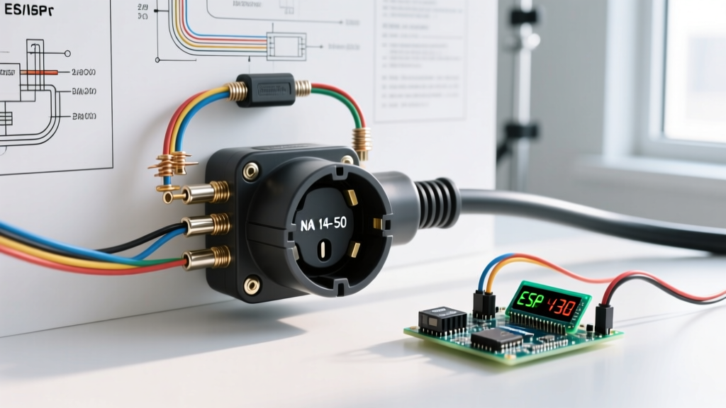
According to the National Fire Protection Association (NFPA), improper installation and degraded 240V receptacles are leading contributors to residential EV charging incidents. This comprehensive inspection and testing guide will walk you through the exact mechanical, electrical, and thermal verification steps required to ensure your NEMA 14-50 or NEMA 6-50 electric car power outlet is safe, code-compliant, and ready for continuous heavy loads.
Phase 1: Visual and Mechanical Inspection
Before any electrical testing begins, a thorough physical inspection of the receptacle and the wiring terminations is mandatory. Many homeowners and inexperienced electricians mistakenly install standard residential-grade 14-50R receptacles (which cost around $15) for EV charging. These are not designed for continuous 40A loads.
1. Verify the Receptacle Grade
Check the model number stamped on the receptacle yoke. For a safe electric car power outlet, you must use an Industrial Grade or EV-specific receptacle. Recommended models include the Hubbell 9450A (approx. $85) or the Leviton 213PR-000 (approx. $75). These feature heavy-duty brass contacts and high-heat thermoplastic housings that resist melting under continuous thermal load.
2. Inspect Wire Terminations and Torque
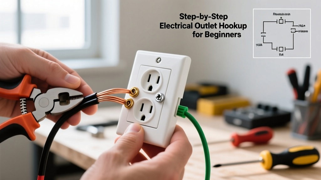
Remove the faceplate and carefully pull the receptacle from the gang box. Inspect the following:
- Wire Strip Length: Ensure no bare copper is exposed outside the terminal block. Exposed copper creates an arc-flash and short-circuit hazard.
- Strand Integrity: Verify that no copper strands were cut or folded back during stripping. A 6 AWG wire missing 20% of its strands will create a localized hot spot.
- Torque Verification: This is the most skipped step. NEC 110.14(D) requires terminations to be torqued to the manufacturer's specifications. Both Hubbell and Leviton mandate 75 in-lbs of torque for their 14-50R terminals. Use a calibrated torque screwdriver (such as the CDI Torque 401SM) to verify. Hand-tightening is insufficient and leads to thermal expansion loosening over time.
Phase 2: Electrical Verification with a Multimeter
Once the mechanical integrity is confirmed, restore power and use a high-quality digital multimeter (DMM) with a CAT III or CAT IV rating, such as the Fluke 87V, to verify the circuit's electrical characteristics. The U.S. Department of Energy's Alternative Fuels Data Center emphasizes that proper voltage and grounding are essential for the EVSE's internal safety relays to engage.
Step-by-Step Voltage Testing Matrix
Set your DMM to AC Voltage (V~). Insert the probes into the receptacle slots and record your readings. Compare them against the expected values for a standard 240V split-phase residential system.
| Test Points | Expected Voltage | Tolerance Range | Purpose of Test |
|---|---|---|---|
| Line 1 (X) to Line 2 (Y) | 240V | 228V - 252V | Confirms both legs of the split-phase breaker are active and delivering full charging voltage. |
| Line 1 (X) to Neutral (W) | 120V | 114V - 126V | Verifies the neutral leg is intact (required for 120V EVSE control circuitry). |
| Line 2 (Y) to Neutral (W) | 120V | 114V - 126V | Confirms balanced split-phase delivery. |
| Line 1 (X) to Ground (U) | 120V | 114V - 126V | Validates the equipment grounding conductor is bonded and active. |
| Line 2 (Y) to Ground (U) | 120V | 114V - 126V | Secondary ground validation. |
| Neutral (W) to Ground (U) | < 2.0V | 0.0V - 1.5V | Checks for neutral-to-ground voltage drop. Readings above 2V indicate an undersized neutral, loose neutral bus bar, or shared neutral overload. |
Phase 3: Thermal Load Testing Under EVSE Draw
A receptacle can pass a static multimeter test but still fail catastrophically under a 40-amp continuous load due to high-resistance connections. Thermal load testing is the definitive way to evaluate your electric car power outlet.
The 45-Minute Load Protocol
- Initiate Charging: Plug in your EV or use a dedicated 40A/50A dummy load tester. Ensure the vehicle is set to draw maximum amperage (e.g., 32A or 40A).
- Wait for Thermal Equilibrium: Allow the system to charge for a minimum of 45 minutes. It takes time for heat to migrate from the terminal connections through the brass contacts and into the receptacle faceplate.
- Scan with an IR Camera: Use a thermal imaging camera (like the FLIR C5 or Seek Thermal CompactPRO) to scan the receptacle face, the plug head, and the corresponding double-pole breaker in your main panel.
Evaluating Thermal Delta (ΔT)
Do not just look at the absolute temperature; look at the temperature rise (Delta T) above ambient room temperature.
- Normal Operation: A Delta T of 5°C to 15°C (9°F to 27°F) above ambient is normal for heavy loads.
- Warning Zone: A Delta T between 15°C and 30°C indicates degrading contacts, insufficient torque, or a receptacle nearing the end of its mechanical life.
- Critical Failure: A Delta T exceeding 30°C (or any absolute temperature reading over 85°C / 185°F on the plastic faceplate) requires immediate shutdown. The outlet must be replaced, and the wire ends must be cut back and re-stripped to remove oxidized copper.
The GFCI Receptacle Dilemma (NEC Article 625)
When inspecting an electric car power outlet installed after 2017, you must address the Ground Fault Circuit Interrupter (GFCI) requirement. NEC Article 625.54 mandates that all receptacles installed for EV charging must have GFCI protection. In the 2023 and 2026 NEC cycles, this requirement remains strictly enforced for plug-in units.
The Nuisance Tripping Problem: Most high-quality EVSEs (like the ChargePoint Home Flex or Tesla Wall Connector) already contain highly sensitive internal GFCI and ground-monitoring circuitry. Stacking a GFCI breaker or a GFCI 14-50R receptacle on top of an EVSE with internal GFCI often results in 'nuisance tripping' due to minor, harmless capacitive leakage currents inherent in EV battery management systems.
The Expert Solution: If you are experiencing random charging interruptions, the issue is likely double-GFCI conflict. The industry-standard best practice in 2026 is to hardwire the EVSE directly to a junction box, eliminating the receptacle entirely. Hardwiring removes the GFCI receptacle requirement (the EVSE's internal protection suffices), eliminates the physical plug connection (a primary failure point for heat), and allows for a cleaner, safer installation.
Troubleshooting Common EV Outlet Failures
Use this quick-reference matrix to diagnose issues when your EV refuses to charge or the outlet shows signs of distress.
| Symptom | Measurement / Observation | Root Cause | Corrective Action |
|---|---|---|---|
| EVSE shows 'Ground Fault' error immediately upon plug-in. | N-to-G voltage > 2V; or GFCI breaker trips instantly. | Bootleg ground, neutral-ground bond at subpanel, or double-GFCI conflict. | Verify grounding electrode system; remove neutral-ground bond in subpanels; switch to hardwired EVSE. |
| Receptacle faceplate is hot to the touch and smells like ozone/melting plastic. | Thermal camera shows Delta T > 30°C at the plug blades. | Residential-grade receptacle used; loose terminal torque; stranded wire splaying. | Replace with Hubbell 9450A; re-torque to 75 in-lbs; cut back and re-strip wires. |
| Charging starts but drops to zero amps after 10 minutes. | Breaker panel is hot; voltage sags below 210V under load. | Undersized wire (e.g., 8 AWG on a 50A breaker) or failing breaker lugs. | Verify 6 AWG copper or 4 AWG aluminum for 50A circuits; torque breaker lugs to spec. |
| EVSE indicator light blinks 'Fault' but outlet tests fine with DMM. | L1-L2 is 240V, but EVSE internal relay clicks and drops. | High resistance in the neutral wire preventing the EVSE's 120V control board from operating. | Check neutral bus bar in the main panel; ensure neutral wire is not nicked or under-torqued. |
Final Safety and Compliance Reminders
Testing an electric car power outlet involves working near live 240V terminals capable of delivering lethal arc-flash energy. Always wear appropriate PPE, including safety glasses and insulated gloves, when performing live voltage tests. If you are not a licensed electrician, use the data and frameworks in this guide to audit your contractor's work. Ensure your installation complies with NEC Article 625, specifically the 125% continuous load derating rule (a 40A EVSE requires a 50A breaker and wire rated for 50A). By prioritizing industrial-grade components, precise torque, and thermal verification, you guarantee a safe, efficient, and fire-free charging experience for the lifespan of your vehicle.