
Decoding the Standard Electrical Wiring Diagram for Light Switch Circuits
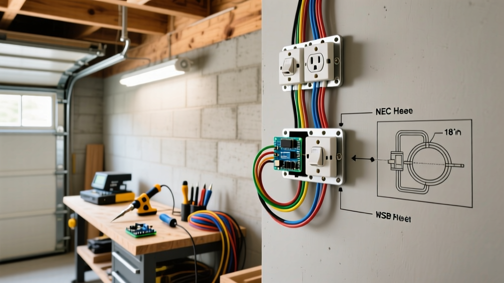
Before you strip a single wire, you must understand the roadmap of your circuit. An electrical wiring diagram for light switch installations is not just a suggestion; it is a critical safety schematic that ensures your home's electrical system operates within the parameters set by the National Electrical Code (NEC). In 2026, with the proliferation of smart home devices and stricter energy codes, understanding these diagrams is more crucial than ever.
For a standard single-pole switch—the most common residential configuration—the diagram dictates the flow of current from the breaker panel to the switch, and finally to the light fixture. Let us break down the core nodes you will encounter on any professional schematic.
Core Schematic Nodes and Real-World Wire Mapping
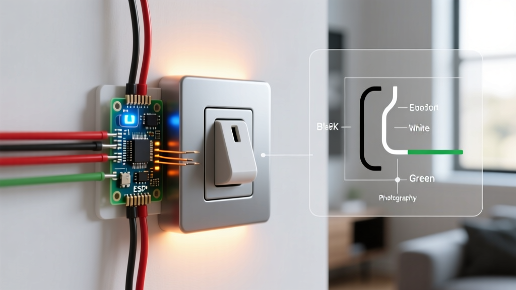
| Diagram Symbol / Label | Real-World Wire Color (NM-B Romex) | Function & NEC Requirement |
|---|---|---|
| Line (Hot) | Black (or Red) | Brings unswitched 120V power from the panel to the switch. Must be connected to the brass or dark-colored 'Line' screw. |
| Load (Switched Hot) | Black (often with red tape) | Carries power from the switch to the fixture only when the switch is closed. Connects to the 'Load' terminal. |
| Neutral | White | Completes the circuit back to the panel. Bypasses the standard switch but must be present in the box per NEC 404.2(C). |
| Ground | Bare Copper or Green | Safety fault path. Must be pigtailed to both the metal box (if applicable) and the green grounding screw on the switch. |
The 'Switch Loop' Diagram Variation
Many older homes (and some newer ones where the power goes to the light fixture first) utilize a 'switch loop'. In this diagram, a 2-wire cable drops from the fixture to the switch. The white wire is used as the Line (Hot), and the black wire is the Load. NEC Article 200.7(C)(2) strictly requires that the white wire used as a hot conductor must be re-identified with black tape or paint at both ends. If your diagram shows power entering the fixture first, expect this configuration.
Tools and Materials for a 2026 Compliant Installation
Skip the generic hardware store kits. To ensure a safe, long-lasting connection that passes municipal inspections, use professional-grade materials. Below is a precise shopping list with estimated 2026 pricing.
| Item | Specific Model / Brand | Estimated Cost | Purpose |
|---|---|---|---|
| Voltage Tester | Fluke 1AC-II VoltAlert | $35.00 | Non-contact verification of dead circuits. |
| Wire Strippers | Klein Tools 11055 (10-18 AWG) | $28.00 | Precision stripping without nicking copper. |
| Single-Pole Switch | Leviton Decora 5601-2W (15A) | $6.50 | Primary switching mechanism with side wire clamps. |
| Wire Connectors | Ideal Wire-Nut 72B (Tan) | $0.15 / ea | Secure pigtailing for ground and neutral bundles. |
| Screwdriver | Wiha 32005 Insulated Phillips #2 | $18.00 | 1000V insulated terminal tightening. |
Step-by-Step Installation Guide
Follow this procedure meticulously. According to the Electrical Safety Foundation International (ESFI), electrical fires and shocks are frequently the result of improper DIY terminations and loose connections.
Step 1: Power Isolation and Lockout
Turn off the 15A or 20A breaker controlling the circuit at the main panel. Do not rely solely on a wall switch. Place a piece of tape over the breaker to prevent accidental re-engagement (a basic Lockout/Tagout practice). Use your Fluke 1AC-II tester on the existing switch faceplate and inside the box to confirm zero voltage. For absolute certainty, verify the tester on a known live circuit before and after testing the dead circuit.
Step 2: Prepping the NM-B Cable
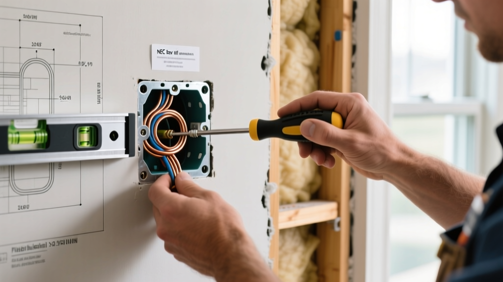
Remove the old switch. If you are installing a new box or extending wires, ensure you have at least 6 inches of wire extending past the front edge of the electrical box (NEC 300.14). Using your Klein Tools strippers, strip exactly 3/4 inch of insulation from the black and white wires. Use the strip gauge molded into the back of the Leviton 5601 switch to verify the length. Pro Tip: Never leave bare copper exposed outside the terminal, and never let insulation get trapped under the terminal screw.
Step 3: Pigtailing the Ground (Crucial for Continuity)
Never daisy-chain the ground wire through the switch itself. Cut a 6-inch piece of bare copper wire (the 'pigtail'). Connect one end of the pigtail to the incoming bare ground wire and the grounding wire of the outgoing cable using an Ideal 72B wire nut. Attach the other end of the pigtail to the green grounding screw on the switch. If you are using a metal electrical box, a second pigtail must connect the ground bundle to the box's grounding clip or 10-32 grounding screw.
Step 4: Terminating Line, Load, and Neutral
Identify your Line (incoming hot) and Load (outgoing to fixture) wires. Wrap the bare copper wire clockwise around the brass terminal screws so that tightening the screw pulls the wire loop tighter. Torque the screws firmly (approx. 12-14 inch-pounds).
WARNING: Avoid 'Backstab' Connections
Many cheap switches feature push-in 'backstab' holes on the rear. These rely on a tiny internal spring clip that can loosen over time due to thermal expansion and arcing, leading to a high-resistance fault and potential fire. Always use the side terminal screws or the screw-clamp plates found on premium models like the Leviton Decora series.
Regarding the Neutral (White) wires: Standard single-pole switches do not connect to the neutral. However, per NFPA 70 (NEC) Article 404.2(C), a neutral wire must be present at the switch box to accommodate future smart switches or timers. Simply bundle the white wires together with a wire nut and tuck them neatly into the back of the box.
Step 5: Box Dressing and Final Testing
Carefully fold the wires into the box. The ground wires should go in first (deepest), followed by the neutrals, and finally the hots and the switch itself. Secure the switch to the box using the provided 6-32 mounting screws. Ensure the strap sits flush against the drywall or plaster. Attach the faceplate, restore power at the breaker, and test the fixture.
Troubleshooting Common Diagram Misinterpretations
Even with a perfect electrical wiring diagram for light switch setups, field conditions can cause confusion. Here is how to diagnose common installation failures:
- Breaker Trips Instantly: You have a dead short. This usually means a ground wire is touching a hot terminal, or the hot and neutral wires are touching inside the box. Re-inspect your wire nut connections and terminal clearances.
- Switch Works 'Backwards' (Up is Off): Single-pole switches are technically bidirectional, but standard convention (and NEC compliance for toggle switches) dictates that 'Up' is 'On'. If it is backwards, the switch was likely mounted upside down. Loosen the mounting screws and rotate the strap 180 degrees.
- Light Flickers When Switch is Off: This is common with LED bulbs on circuits with illuminated switches or improperly wired smart switches leaking a tiny amount of current. Ensure you are using a standard, non-illuminated single-pole switch, or upgrade to an LED-compatible dimmer with a neutral connection.
Frequently Asked Questions (FAQ)
Can I use a 14-gauge wire on a 20-amp breaker circuit?
No. This is a severe fire hazard and a direct violation of NEC Article 240.4(D). A 20-amp breaker requires a minimum of 12 AWG copper wire. If your breaker is 20A, you must use 12/2 NM-B cable and a 20A rated switch (like the Leviton 5602).
Why does my switch box have three black wires?
If you see three black wires (and three whites), your switch box is likely acting as a 'junction' for another downstream circuit. One black is the Line from the panel, one black is the Load to the light, and the third black is the Line continuing to the next outlet or switch. You must identify the downstream hot and pigtail it together with the incoming hot, leaving only the Load wire to connect to the switch terminal.
Do I need an arc-fault (AFCI) breaker for this switch?
Under the current NEC cycle, AFCI protection is required for almost all 120V, 15A and 20A branch circuits supplying outlets and lighting in living areas, bedrooms, kitchens, and hallways. If you are installing a new circuit or replacing an old panel, ensure the breaker powering your switch is an AFCI type to meet modern safety standards, as highlighted by OSHA's electrical safety guidelines for residential and commercial environments.