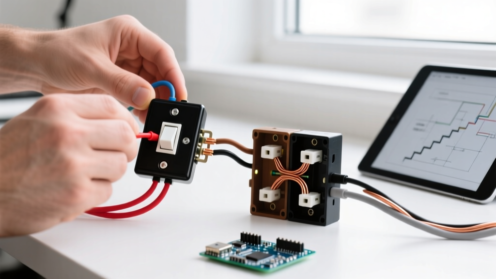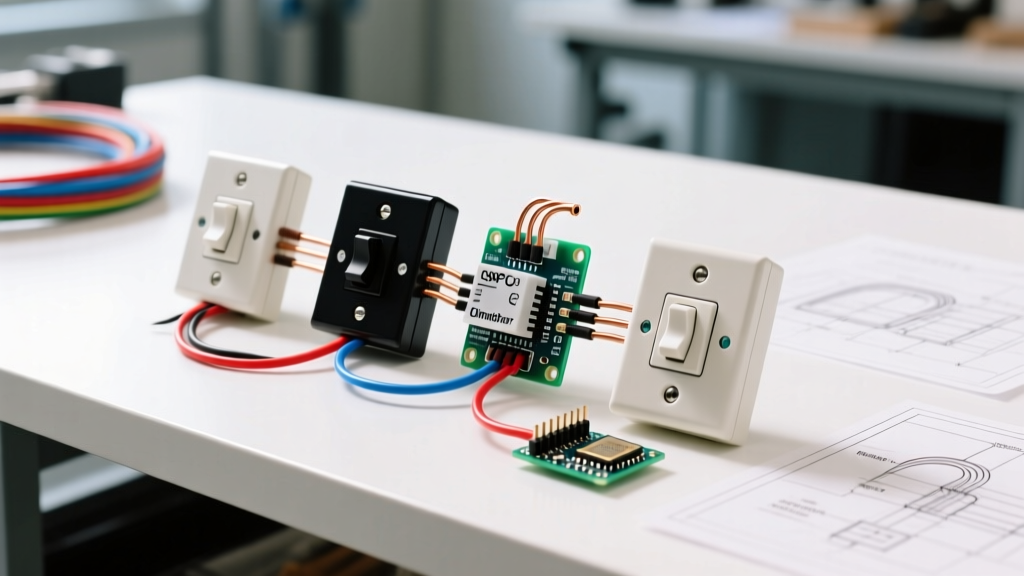

Introduction to 4-Way Dimmer Circuits & NEC Compliance
Wiring a 4-way switch circuit—which allows you to control a single lighting load from three or more locations—is already one of the more complex residential electrical tasks. When you introduce a dimmer into this equation, the complexity multiplies. More importantly, modern National Electrical Code (NEC) requirements have fundamentally changed how these circuits must be designed and executed. As we navigate the 2026 enforcement cycles of the 2023 NEC, electricians and advanced DIYers must pay strict attention to neutral wire availability, box fill calculations, and LED compatibility.
This guide serves as a comprehensive code requirement explainer and provides a practical wiring diagram for 4 way switch with dimmer configurations. We will break down exact product specifications, cubic inch box fill mathematics, and the critical NEC articles that dictate where your dimmer can legally and safely be installed.
⚠️ NEC 404.2(C) CRITICAL UPDATE: Under current NEC guidelines, snap switches (including dimmers) that require a neutral wire for their internal electronics must be installed in switch boxes that contain a neutral conductor. You cannot artificially create a neutral using the equipment grounding conductor, nor can you use a grounding electrode. If your intermediate 4-way boxes lack a neutral, you cannot install a standard neutral-required dimmer there.
The Core Code Hurdle: Where to Place the Dimmer?
In a standard 4-way circuit, power typically enters at the first 3-way switch (Line Box), travels through two traveler wires to the 4-way switch (Intermediate Box), then through two more travelers to the final 3-way switch (Load Box), which then feeds the light fixture. Because standard NM-B (Romex) cable wiring methods often only pass the hot and travelers through the intermediate boxes, the neutral wire is frequently absent in the 4-way box and the far-end 3-way box.
This absence of a neutral creates a major roadblock for modern LED dimmers, such as the Lutron Diva DVCL-153P (retailing around $28-$35) or the Leviton Decora Smart DW4SF ($45-$50), which require a neutral to power their internal microprocessors and prevent LED ghosting.
Dimmer Placement Strategies & Code Compliance
| Strategy | Placement Location | NEC Compliance & Neutral Status | Recommended Hardware |
|---|---|---|---|
| Line-Side Standard Dimmer | First 3-way box (Power Source) | Compliant. Neutral is present at the panel feed. Handles full load. | Lutron Maestro MACL-LFQ (Line/Load capable) |
| Load-Side Standard Dimmer | Last 3-way box (Fixture Feed) | Compliant. Neutral is present via the fixture cable. Must be rated for load-side. | Lutron Diva DVCL-153P (Wired for Load) |
| Smart Dimmer + Companions | Dimmer at Line/Load; Companions at 4-way | Highly Compliant. Companions (like Lutron PD-5S-DV) do not require local neutrals in the same way, or use wireless communication. | Lutron Caseta Smart Bridge + Pico Remotes |
Step-by-Step Wiring Diagram for 4 Way Switch with Dimmer (Line-Side)
The most reliable and code-compliant method for integrating a standard dimmer into a 4-way circuit is placing the dimmer at the Line-Side (Power Source) 3-way box. This ensures the dimmer has access to the main neutral bundle and the unswitched hot line.
Preparation and Safety
- De-energize the Circuit: Turn off the breaker and verify zero voltage using a non-contact voltage tester and a multimeter at the line box.
- Identify Conductors: Use a voltage sniffer or multimeter to identify the unswitched Line Hot (usually black), the Neutral bundle (white), and the Ground (bare/green).
- Mark Travelers: While the NEC does not strictly mandate traveler colors, industry best practice (and NFPA NEC guidelines recommendations for clarity) suggests tagging the traveler wires with yellow or orange electrical tape to distinguish them from the switched leg.
Executing the Line-Side Dimmer Wiring
- Connect the Ground: Attach the dimmer’s green ground wire to the bare copper ground bundle in the box using a wire nut or Wago lever connector.
- Connect the Neutral: Connect the dimmer’s white neutral wire to the existing bundle of white neutral wires in the box. Do not connect this to the white traveler wire.
- Connect the Line Hot: Attach the dimmer’s black (or designated Line) wire to the unswitched hot wire coming from the breaker panel.
- Connect the Travelers: Attach the dimmer’s two traveler wires (often blue and yellow, or red and white with tape) to the two traveler wires of the /3 NM-B cable heading toward the 4-way switch.
- Wire the 4-Way and Load-Side 3-Way: The intermediate 4-way switch simply passes the travelers straight through or crosses them. The final 3-way switch connects the incoming travelers to its traveler screws, and its common screw connects to the black switched hot wire heading up to the light fixture.
Box Fill Calculations: Avoiding NEC 314.16 Violations
One of the most frequently failed inspections in 4-way switch circuits is box fill. A 4-way switch box contains a massive amount of wire volume. Under NEC Article 314.16, every conductor, clamp, and device yoke counts toward the cubic inch capacity of the electrical box.
Real-World Box Fill Math (12 AWG Circuit)
Let’s calculate the box fill for an intermediate 4-way switch box using 12 AWG wire (which requires 2.25 cubic inches per conductor count).
- 4 Traveler Wires: 4 counts × 2.25 = 9.0 cu in.
- 1 Ground Bundle: 1 count × 2.25 = 2.25 cu in.
- 4-Way Switch Device: 2 counts × 2.25 = 4.5 cu in.
- Internal Cable Clamps: 1 count × 2.25 = 2.25 cu in.
- Total Minimum Box Volume: 18.0 cubic inches.
A standard single-gang nail-on box is typically 14 to 16 cubic inches, which is a direct code violation for a 12 AWG 4-way setup. You must use a deep single-gang box (like the Raco 2900 at 22 cu in) or a 2-gang box with a mud ring to legally accommodate the volume. For authoritative box fill tables, always refer to the latest edition of the NEC or training resources provided by the Electrical Training Alliance.
Common Failure Modes & Troubleshooting
Even with a perfect wiring diagram for 4 way switch with dimmer execution, modern LED lighting can present unique challenges. Here are specific failure modes and their solutions:
- LED Ghosting / Glow When Off: This occurs when a dimmer leaks a tiny amount of current to power its internal locator LED or microprocessor, which is enough to partially illuminate highly efficient LEDs. Fix: Ensure the dimmer's neutral wire is connected to the actual neutral bundle, not the ground. If using a non-neutral dimmer, install a Lutron LUT-MLC (Minimum Load Capacitor) across the first and last fixture in the circuit.
- Pop-On / Snap-On Behavior: The lights do not dim smoothly from 0% but instead snap on at 20%. Fix: Adjust the low-end trim potentiometer on the dimmer (using the small set-screw on Lutron models) to match the specific LED driver's minimum voltage threshold.
- Audible Buzzing at Mid-Range: Caused by pulse-width modulation (PWM) conflicts between the dimmer's triac and the LED driver's internal circuitry. Fix: Swap the dimmer for a model specifically tested for your bulb brand. Lutron maintains an extensive, publicly accessible LED compatibility matrix on their Technical Support portal to match exact bulb SKUs with compatible dimmers.
Final Code & Safety Takeaways
Integrating a dimmer into a 4-way switch circuit requires more than just following a basic schematic; it demands a thorough understanding of modern NEC neutral requirements and box fill limitations. By strategically placing your primary dimmer at the line-side or load-side box where neutrals are guaranteed, and utilizing deep junction boxes to accommodate traveler wire volume, you ensure a safe, code-compliant, and flicker-free lighting installation. Always consult with a licensed electrician or your local AHJ (Authority Having Jurisdiction) if your existing wiring lacks the necessary neutral conductors to support modern dimming technology.