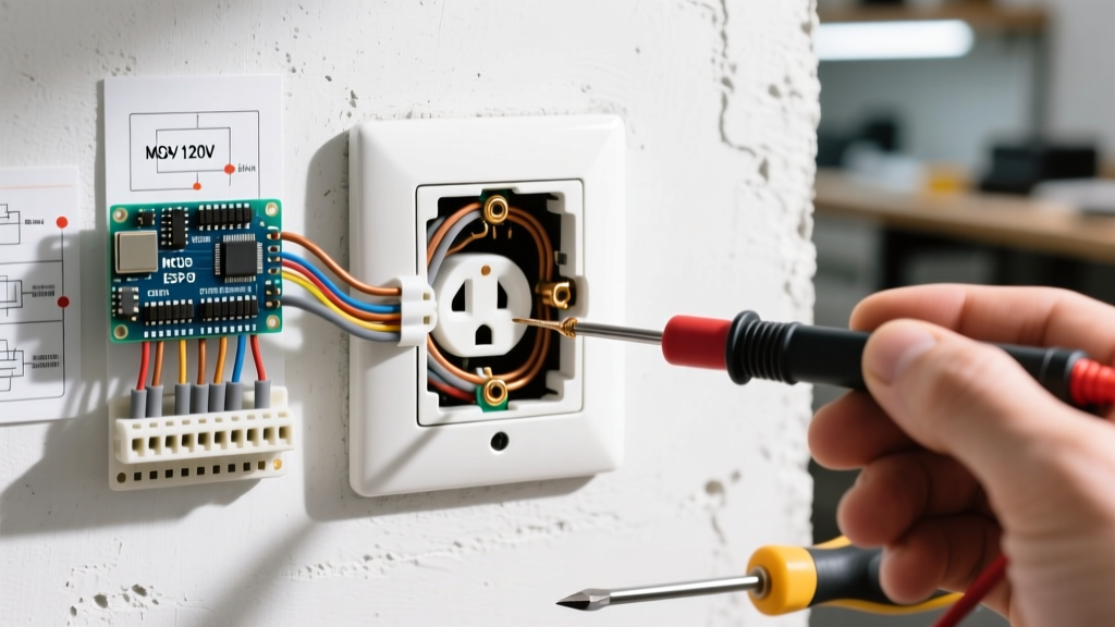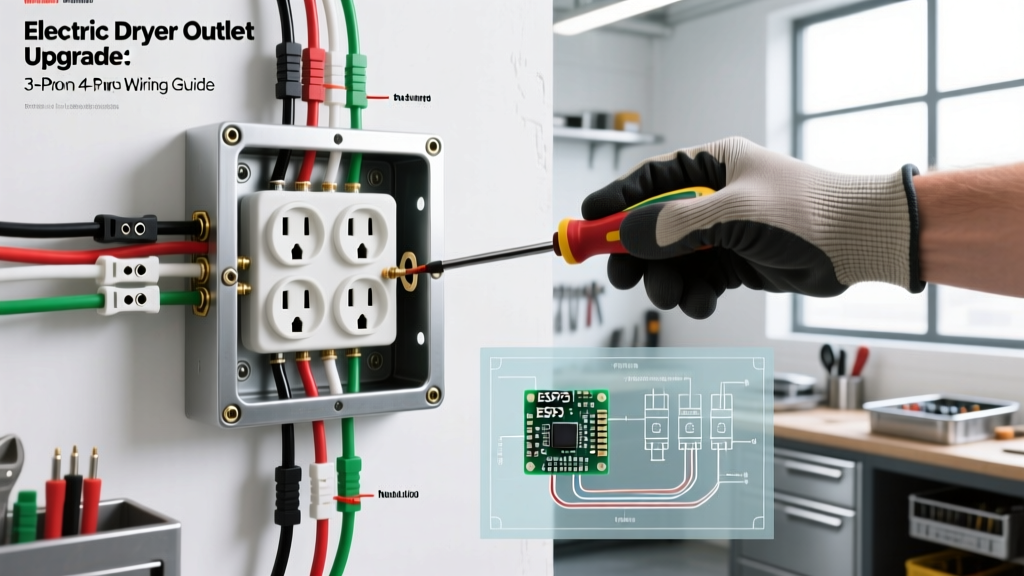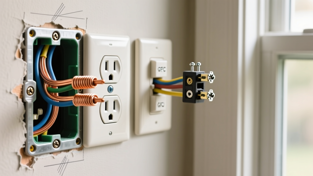

When it comes to residential electrical upgrades, installing a new electrical outlet is one of the most common yet frequently misunderstood tasks. Whether you are adding a receptacle to a finished wall for a home office, extending a circuit to a kitchen island, or upgrading an aging two-prong receptacle to a modern grounded GFCI, the underlying physics and National Electrical Code (NEC) requirements remain uncompromising. A poorly terminated wire can lead to high-resistance connections, arcing, and ultimately, electrical fires.
This guide bypasses generic advice and dives deep into the technical realities, specific product selections, and exact wiring scenarios you will encounter in the field. Before touching any wire, always verify the circuit is de-energized using a reliable non-contact voltage tester, such as the Klein Tools NCVT-3, and lock out the breaker panel.
Evaluating Circuit Capacity Before Expanding
Before installing a new electrical outlet, you must verify that the existing circuit has the thermal headroom to support the additional load. The NEC mandates that continuous loads (those operating for 3 hours or more) must not exceed 80% of the circuit breaker's rating.
- 15-Amp Circuit (14 AWG wire): Maximum continuous load of 1,440 watts.
- 20-Amp Circuit (12 AWG wire): Maximum continuous load of 1,920 watts.
If you are tapping into a 15-amp bedroom circuit that already powers a 1,200-watt space heater and a 300-watt desktop PC, adding a new outlet for another high-draw device will trip the breaker. Always map the existing loads before extending the run.
Scenario A: Extending an Existing Receptacle (Daisy-Chaining vs. Pigtailing)
The most frequent scenario for installing a new electrical outlet involves extending power from an existing, nearby receptacle. While many DIYers simply wire the new cable directly into the 'LOAD' terminals of the existing outlet (daisy-chaining), this is considered a substandard practice by master electricians.
The Pigtail Method
When you daisy-chain through the receptacle's yoke, the entire downstream circuit relies on the physical integrity of the brass terminal screws and the metal strap of the device. If the original receptacle fails or is removed, the downstream outlet loses power. Furthermore, it places two wires under a single screw terminal, which is prohibited by most manufacturers unless the device features specific screw-clamp plates.
The Expert Solution: Use the pigtail method. Strip the existing LINE wires, the new downstream wires, and a 6-inch pigtail of the same gauge. Connect them using Wago 221-413 lever nuts or copper crimp sleeves. Attach the single pigtail to the receptacle's LINE terminal. This ensures the original device and the new outlet operate independently on the same parallel circuit.
Scenario B: Cutting Into Finished Drywall (Old-Work Installations)
Installing a new electrical outlet in a finished room requires 'old-work' (retrofit) boxes and careful cable fishing. The Carlon B114R 1-gang old-work box is an industry standard, featuring adjustable wings that clamp securely against 1/2-inch to 5/8-inch drywall.
- Locate Studs and Obstructions: Use a magnetic stud finder to map the framing. Ensure there are no plumbing lines or HVAC ducts directly behind your cut line.
- Cut the Opening: Trace the face of the old-work box on the drywall. Cut slightly inside the line using a drywall saw or a rotary tool with a drywall bit to ensure a snug fit.
- Fish the NM-B Cable: Use fiberglass fish tapes or glow rods to route the 12/2 or 14/2 NM-B (Romex) cable from the source box to the new opening. Leave at least 8 inches of cable protruding from the box to satisfy NEC 300.14 requirements.
- Secure the Box: Feed the cable through the integrated Romex clamps of the Carlon box, insert the box into the wall, and tighten the mounting screws until the plastic wings flip and pull tight against the back of the drywall.
2026 NEC Code Compliance: GFCI and AFCI Mandates
When installing a new electrical outlet, you must adhere to the latest NEC cycles (adopted progressively through 2026). According to the National Fire Protection Association (NFPA), ground-fault and arc-fault protection are no longer optional in critical areas.
Code Alert: NEC Article 210.8 requires GFCI protection for all 125V to 250V receptacles in kitchens, bathrooms, garages, crawlspaces, unfinished basements, and outdoor areas. NEC Article 210.12 mandates AFCI protection for almost all living spaces, including bedrooms, living rooms, and hallways.
If you are replacing a standard receptacle in a bedroom, you must install an AFCI receptacle (e.g., Leviton AFAFTR1-W). In kitchens or garages, a GFCI receptacle like the Eaton GFNT1-W is required. For areas requiring both (like a kitchen island), use a dual-function AFCI/GFCI receptacle (e.g., Leviton AGFTR1-W), which retails between $35 and $45.
Receptacle Selection Matrix
Choosing the correct receptacle amperage and configuration is critical for safety and code compliance. Refer to the table below before purchasing materials.
| Receptacle Type | Amperage | Wire Gauge | Avg. Cost (2026) | Primary Application |
|---|---|---|---|---|
| Standard Duplex (15A) | 15 Amp | 14 AWG or 12 AWG | $1.50 - $3.00 | Bedrooms, living rooms, hallways |
| Standard Duplex (20A) | 20 Amp | 12 AWG (Strictly) | $2.50 - $4.50 | Kitchens, dining rooms, garages |
| GFCI (Ground Fault) | 15A / 20A | 14 AWG / 12 AWG | $15.00 - $25.00 | Bathrooms, outdoors, basements |
| AFCI/GFCI Combo | 15A / 20A | 14 AWG / 12 AWG | $35.00 - $48.00 | Kitchen islands, laundry rooms |
| Isolated Ground (IG) | 15A / 20A | 12 AWG + Extra Ground | $8.00 - $12.00 | Medical facilities, sensitive AV |
Precision Wiring: Termination and Torque Specifications
The physical termination of the copper conductor to the brass terminal screw is where most residential failures occur. The Occupational Safety and Health Administration (OSHA) frequently cites improper electrical connections as a leading cause of workplace and residential thermal events.
Strip Length and the Shepherd's Hook
Use the strip gauge molded into the back of the receptacle body. For most Leviton and Eaton devices, this is exactly 5/8 of an inch. Stripping too little leaves exposed insulation under the screw head, increasing resistance. Stripping too much leaves bare, live copper exposed outside the terminal, creating a shock hazard.
Form a 'shepherd's hook' in the stripped wire using needle-nose pliers. Hook the wire around the terminal screw clockwise. This ensures that as you tighten the screw, the loop pulls closed rather than splaying open.
The Importance of Torque Screwdrivers
Hand-tightening terminal screws is an outdated practice. Under-tightening causes micro-movements that lead to arcing and heat buildup. Over-tightening strips the brass threads or snaps the screw head. Modern UL-listed receptacles specify exact torque values, typically between 12 and 16 inch-pounds. Invest in a calibrated torque screwdriver, such as the Klein Tools 69010, set to the manufacturer's specification (usually 14 in-lbs for standard 15A/20A devices).
Push-In Backstab vs. Screw Terminals
Many commercial-grade and residential receptacles feature push-in 'backstab' terminals on the rear. While the NEC permits their use on 15-amp circuits with 14 AWG solid copper wire, experienced electricians overwhelmingly avoid them. Backstab connections rely on a small internal spring-metal tang to grip the wire. Over years of thermal expansion and contraction, these springs can lose tension, resulting in a high-resistance connection that melts the plastic housing.
Best Practice: Always use the side-wire screw terminals. If you are working with 12 AWG wire, backstabbing is strictly prohibited by code and the physical hole will not accept the thicker gauge. If speed is a concern on a large commercial job, use devices equipped with internal screw-clamp plates (often found on Leviton's commercial spec-grade lines), which clamp the wire securely when the screw is tightened.
Testing and Troubleshooting Edge Cases
Once the outlet is mounted and the cover plate is installed, do not assume the job is complete. Plug in a dedicated circuit tester, such as the Gardner Bender GRT-501. This $12 tool will instantly verify correct wiring.
Common Failure Modes
- Open Ground: The tester shows a ground fault. This usually means the bare copper ground wire was not securely terminated to the green grounding screw, or the grounding path back to the panel is broken. In old-work scenarios, ensure the ground wire is bonded to the metal box (if applicable) using a green grounding clip or pigtail.
- Reversed Polarity (Hot/Neutral Swap): The white neutral wire was accidentally placed on the brass (hot) terminal, and the black hot wire on the silver (neutral) terminal. While the device may still power a lamp, it creates a severe shock hazard because the internal switch of the plugged-in appliance will break the neutral rather than the hot leg.
- Open Neutral: Often caused by a failed backstab connection upstream or a loose wire nut in the junction box. The outlet will show dead, but a non-contact voltage tester may still detect an induced 'phantom' voltage on the hot wire.
For comprehensive safety standards regarding residential receptacles and ground-fault protection, always consult the Consumer Product Safety Commission (CPSC) Electrical Safety Center. Installing a new electrical outlet is a highly rewarding DIY project, provided you respect the physics of the connection and the strict letter of the electrical code.