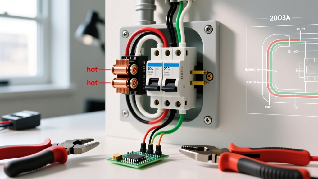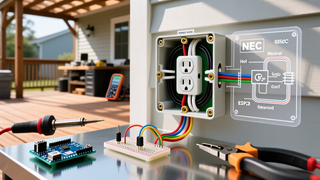

The Modern Standard: Wiring an Electric Range Outlet
Installing a high-amperage 240-volt receptacle for a kitchen range is one of the most critical residential electrical tasks. Unlike standard 120V branch circuits, an electric range demands a dedicated 50-amp, double-pole circuit capable of delivering sustained power to high-wattage heating elements and convection fans. As of the 2026 National Electrical Code (NEC) adoption cycle, the industry has fully transitioned away from legacy three-prong configurations in favor of isolated grounding systems.
This wiring diagram reference provides exact terminal mappings, wire gauge requirements, and torque specifications for installing a NEMA 14-50R (four-prong) electric range outlet, while also documenting the legacy NEMA 10-50R (three-prong) for troubleshooting and code-compliance verification.
NEMA 14-50R vs. NEMA 10-50R: Code Compliance Matrix
Before pulling wire, it is vital to understand the legal and safety distinctions between the two common range receptacles. The National Fire Protection Association (NFPA) mandates the separation of the neutral and equipment grounding conductors for all new installations.
| Feature | NEMA 14-50R (Four-Prong) | NEMA 10-50R (Three-Prong) |
|---|---|---|
| Installation Status | Mandatory for all new construction (Post-1996 NEC) | Grandfathered only; illegal for new installs |
| Wire Configuration | Hot 1, Hot 2, Neutral, Ground (4-wire) | Hot 1, Hot 2, Combined Neutral/Ground (3-wire) |
| Standard Cable | 6/3 NM-B with Ground (Copper) or 4/3 SER (Aluminum) | 6/2 NM-B (Legacy) or 10/3 NM-B (Misapplied) |
| Safety Risk Profile | Low (Isolated ground prevents chassis energization) | High (Broken neutral energizes range chassis to 120V) |
| Breaker Requirement | 50A Double-Pole (240V) | 50A Double-Pole (240V) |
Wiring Diagram Reference: Four-Prong NEMA 14-50R
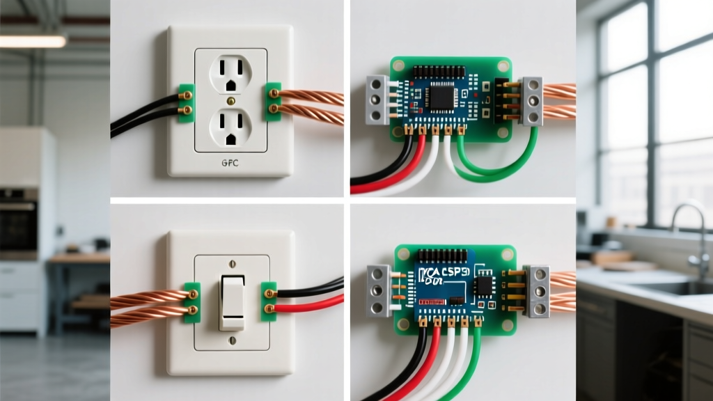
The NEMA 14-50R receptacle features four distinct slots: a U-shaped ground pin at the bottom (or top, depending on orientation), a straight neutral blade, and two angled hot blades. When wiring the receptacle, you must map the circuit conductors to the correct terminal designations stamped on the back of the yoke.
Terminal Mapping and Wire Color Coding
- Terminal 'G' (Ground): Connect the bare copper (or green) equipment grounding conductor. This is the U-shaped pin. It provides a dedicated, low-impedance fault path back to the main panel's ground bus.
- Terminal 'W' (Neutral/White): Connect the white insulated neutral conductor. This blade is the straight vertical slot. It carries the 120V return current for the range's clock, control board, and interior lighting.
- Terminal 'X' (Hot 1 / Black): Connect the black insulated hot conductor. This corresponds to the left angled blade (when facing the receptacle with the ground pin at the bottom). Carries 120V from Leg A of the split-phase panel.
- Terminal 'Y' (Hot 2 / Red): Connect the red insulated hot conductor. This corresponds to the right angled blade. Carries 120V from Leg B. Together, X and Y provide the 240V required for the baking and broiling elements.
Expert Note on Orientation: While the NEC does not explicitly mandate the orientation of the ground pin (up or down), the 2026 industry best practice—and the requirement in many local jurisdictions—is to install the receptacle with the ground pin facing up. This prevents a falling metal object (like a range hood screw or a cooking utensil) from bridging the gap between the hot blades if the plug is partially pulled out.
Wiring Diagram Reference: Three-Prong NEMA 10-50R (Legacy)
If you are troubleshooting an older home, you may encounter a NEMA 10-50R. This receptacle lacks a dedicated equipment grounding conductor. Instead, it relies on the neutral wire to serve as both the 120V return path and the chassis ground via a bonding strap on the back of the range.
Legacy Terminal Mapping
- Center Terminal (Neutral/Ground): The white (or bare, in severe code violations) wire connects here. This is the most dangerous point of failure in a legacy system.
- Outer Terminals (Hot 1 & Hot 2): Black and Red wires connect to the angled outer blades.
Failure Mode Analysis: If the neutral connection at the receptacle or the panel corrodes or loosens, the 120V return current seeks an alternative path. Because the range chassis is bonded to the neutral, the entire metal exterior of the oven becomes energized at 120V, presenting a lethal shock hazard. According to the U.S. Consumer Product Safety Commission (CPSC), upgrading legacy three-prong range outlets to four-prong configurations significantly reduces residential electrocution risks.
Step-by-Step Installation and Torque Specifications
Proper installation requires more than just matching colors to terminals. High-amperage circuits generate significant heat, making mechanical termination integrity paramount.
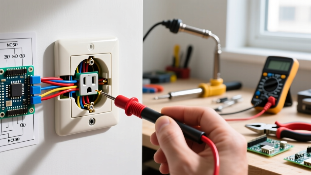
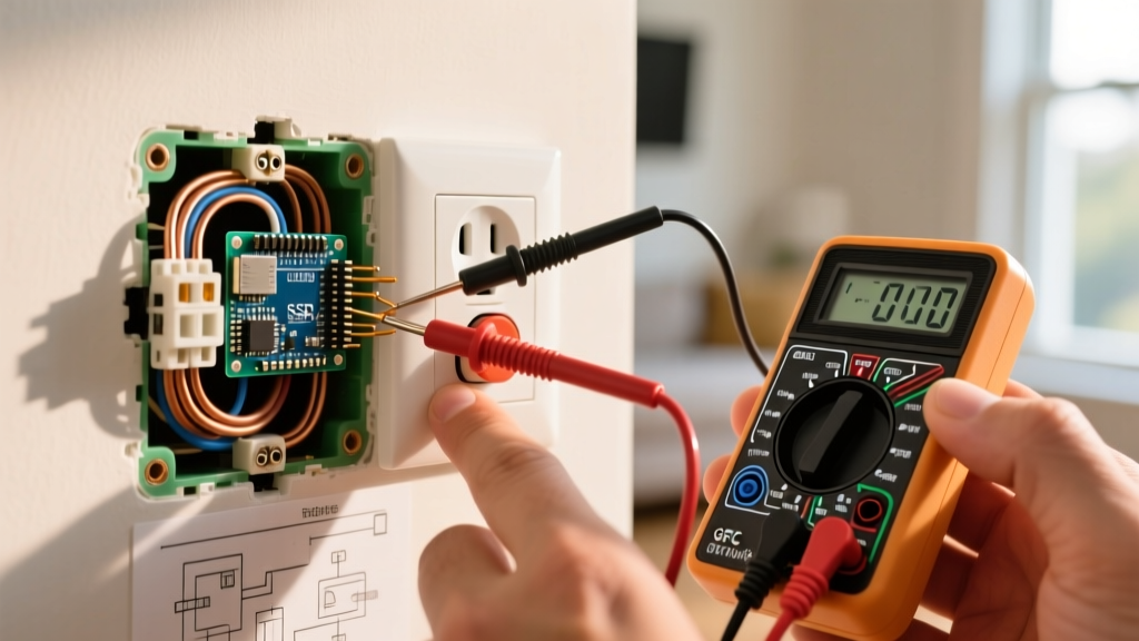
- Verify Power Isolation: Lock out the 50A double-pole breaker. Verify zero voltage using a CAT III or CAT IV rated digital multimeter. Test between both hot legs (should read 0V) and from each hot leg to ground (should read 0V).
- Prepare the Conductors: Strip exactly 5/8-inch of insulation from the 6 AWG copper wires. Do not nick the copper; scoring the wire creates a resistive hot-spot that will degrade over time under 40A+ continuous loads.
- Apply Anti-Oxidant (If Aluminum): If you are running 4 AWG aluminum SER cable, you must brush the exposed aluminum strands with Noalox or a similar zinc-dust anti-oxidant compound before termination. Aluminum oxidizes rapidly, creating a high-resistance layer that causes terminal fires.
- Terminate and Torque: Insert the wires into the NEMA 14-50R terminals. NEC Article 110.14(D) strictly requires the use of a calibrated torque screwdriver for terminations. For standard 50A Leviton (Model 279-S00) or Hubbell (Model 9450A) receptacles, torque the terminal screws to 20 inch-pounds. Under-torquing causes arcing; over-torquing strips the brass threads or shears the screw head.
- Secure the Cable: If using 6/3 NM-B (Romex), secure the cable with an appropriate clamp within 12 inches of the steel junction box. The cable jacket must extend into the box by at least 1/4 inch to protect the wire insulation from the sharp metal edges of the box knockout.
- Mount and Test: Secure the receptacle to the box using the provided #6-32 mounting screws. Restore power and test the receptacle with a dedicated 240V receptacle tester or a multimeter (expect 240V across X-Y, and 120V across X-W and Y-W).
2026 Material and Cost Breakdown
When budgeting for a new range circuit installation, material costs have stabilized following the copper price fluctuations of the early 2020s. Below is a realistic material breakdown for a standard 30-foot run from the main panel to the kitchen.
| Component | Specification / Model | Estimated 2026 Cost |
|---|---|---|
| Wire (Copper) | 6/3 NM-B with Ground (30 ft) | $55.00 - $75.00 |
| Circuit Breaker | 50A Double-Pole (Square D Homeline / Siemens) | $45.00 - $60.00 |
| Receptacle | Leviton 279-S00 NEMA 14-50R (Flush Mount) | $14.00 - $18.00 |
| Junction Box | 2-Gang Masonry or Steel Stud Box (Deep) | $6.00 - $12.00 |
| Faceplate | Thermoset or Stainless Steel 2-Gang | $3.00 - $15.00 |
| Total Materials | Excluding labor and drywall repair | $123.00 - $180.00 |
Troubleshooting Edge Cases and Failure Modes
Even with perfect wiring diagrams, field conditions introduce variables. Here are specific failure modes encountered during range outlet commissioning:
The 'Phantom 120V' on the Ground Wire
If you measure 120V between the Hot (X or Y) and the bare Ground wire, but 0V between the Neutral (W) and Ground (G), your circuit is functioning normally. However, if you measure voltage between the Neutral and Ground, you have a bootleg ground or a shared neutral fault upstream. In a properly wired NEMA 14-50 circuit, the neutral carries unbalanced current, and the ground carries zero current. Any voltage drop on the ground wire indicates a severe safety violation.
Range Elements Fail to Heat, but Clock Works
This indicates a loss of one of the 240V hot legs. The control board (120V) is receiving power from the surviving hot leg and the neutral, but the 240V heating elements cannot complete the circuit. Diagnostic Step: Check the 50A double-pole breaker. If one pole has tripped internally without moving the handle (a rare but documented failure in aging thermal-magnetic breakers), the breaker must be replaced. Do not simply reset it; internal pole-failure requires immediate hardware replacement.
Terminal Discoloration and Melting
If you are replacing an existing outlet and notice brown or black melting around the 'X' or 'Y' terminals, this is the direct result of thermal cycling due to under-torqued connections. As the range cycles on and off, the loose wire expands and contracts, slowly backing out of the terminal. This increases electrical resistance, generating intense localized heat. Always cut back the damaged wire to fresh, clean copper before terminating the new receptacle, and strictly adhere to the 20 in-lbs torque specification.