
Understanding the Modern Code Requirements for Your Electrical Outlet
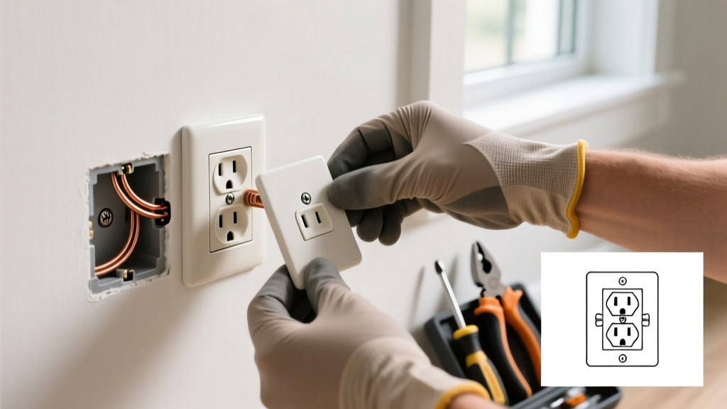
Installing a standard 15-amp electrical outlet is a foundational DIY electrical task, but modern code requirements and safety standards have evolved significantly. As of the 2023 National Electrical Code (NEC) and continuing into 2026 local adoptions, virtually all 15-amp and 20-amp, 125-volt and 250-volt receptacles installed in dwelling units must be Tamper-Resistant (TR). According to the Electrical Safety Foundation International (ESFI), TR receptacles feature built-in safety shutters that prevent children from inserting foreign objects into the slots, reducing the risk of severe shock and burns.
NEC Article 406.12: All nonlocking type 15- and 20-ampere, 125- and 250-volt receptacles installed in dwelling units shall be listed and identified as tamper-resistant receptacles.
While the initial insertion force for a TR electrical outlet is slightly higher than older models, the safety benefits are non-negotiable. This guide details the exact procedure for wiring a 15-amp TR duplex receptacle, focusing on professional termination techniques that prevent loose connections and arc faults.
Professional-Grade Tools and Materials
Skip the bargain-bin tools. Electrical connections rely on precise mechanical pressure. Here is the exact loadout required for a code-compliant installation:
- Receptacle: Leviton Decora 15A TR (Model T5262-E). Retails for approximately $2.50 to $3.50 per unit in 2026. Features side-wire terminal screws and back-wire clamps.
- Wire Strippers: Klein Tools 11055 (10-18 AWG). Precision stripping prevents nicking the copper conductor, which creates a weak point prone to snapping under torque.
- Connectors: Wago 221-413 Lever-Nuts. Superior to traditional twist-on wire nuts for pigtailing, offering a verifiable, gas-tight connection.
- Torque Screwdriver: CDI Torqmaster or Wiha set to 14 in-lbs. NEC 110.14(D) requires terminals to be tightened to the manufacturer's specified torque.
- Tester: Gardner Bender GRT-300 or a standard 3-light receptacle tester paired with a Fluke 117 True-RMS Multimeter for voltage verification.
Step-by-Step Electrical Outlet Installation
Step 1: De-Energize and Verify the Circuit
Locate the correct breaker in your main panel and switch it to the OFF position. Do not rely solely on a non-contact voltage tester (NCVT). Use a multimeter set to AC Voltage (V~) to test between the black (hot) and white (neutral) wires, and then between the black and bare (ground) wires. The reading must be exactly 0.0V. For a comprehensive overview of NEC safety standards, refer to the NFPA 70 catalog.
Step 2: Prepare the Conductors
Inspect the incoming Romex (NM-B) cable. For a 15-amp circuit, you must use 14 AWG copper wire; for a 20-amp circuit, 12 AWG is mandatory. Using the strip gauge printed on the back of the Leviton T5262-E, strip exactly 3/4-inch (19mm) of insulation from the black, white, and ground wires. Crucial Edge Case: If the existing wire insulation is brittle or cracked from decades of heat exposure, cut back to healthy wire. If this leaves you with less than 3 inches of wire protruding from the box, you must use a junction box extension or a Wago lever-nut to pigtail an extension, as NEC 300.14 requires at least 3 inches of free conductor length.
Step 3: Form the Shepherd's Hook
Using needle-nose pliers, bend the stripped end of each solid copper wire into a 'J' or 'Shepherd's hook' shape. The loop must be perfectly round so it wraps snugly around the terminal screw shaft without overlapping the insulation or extending past the screw head, which creates an exposed shock hazard.
Step 4: Terminate the Connections
Follow the standard color-coding protocol:
- Ground: Connect the bare/green wire to the green grounding screw at the bottom of the yoke.
- Neutral: Connect the white wire to the silver terminal screw.
- Hot: Connect the black wire to the brass terminal screw.
Hook the wire around the screw in a clockwise direction. As you tighten the screw with your torque screwdriver set to 14 in-lbs, the clockwise motion ensures the wire loop pulls tighter under the screw head rather than being pushed outward. If your receptacle features 'back-wiring' clamp plates (common on commercial-grade spec outlets), you can insert the straight-stripped wire into the rear hole and tighten the screw to engage the clamp. This is code-compliant and highly secure, unlike 'push-in' backstab holes found on cheap builder-grade outlets.
Step 5: Secure and Align the Yoke
Carefully fold the wires into the back of the electrical box in a 'Z' pattern (grounds first, then neutrals, then hots). Mount the receptacle using the provided 6-32 machine screws. Use the leveling slots on the yoke to ensure the outlet sits perfectly straight before tightening. Install a screwless Decora wall plate for a clean, modern finish.
Wiring Configurations: Standard vs. Split-Wired
Not every electrical outlet is wired identically. In living rooms and bedrooms, you may encounter a 'split-wired' or 'switched' receptacle where the top half is controlled by a wall switch and the bottom half remains constantly hot.
| Configuration | Yoke Fin Tab Status | Wiring Setup | Common Application |
|---|---|---|---|
| Standard Duplex | Brass and Silver tabs INTACT | One black and one white wire connected to respective screws. | Kitchens, bathrooms, general purpose rooms. |
| Split-Wired (Switched) | Brass tab BROKEN; Silver tab INTACT | Two black wires (one constant hot, one switched hot) to brass screws; one white to silver. | Living room lamps controlled by a wall switch. |
| Multi-Wire Branch (MWBC) | Brass tab BROKEN; Silver tab INTACT | Two hots from different phases (240V between them) share one neutral. Requires handle-tied breakers. | Kitchen countertop small-appliance circuits. |
Pro Tip: If you are replacing a split-wired outlet and forget to break the brass connecting fin tab using pliers, the wall switch will either fail to operate the lamp, or worse, it will create a dead short between the constant hot and switched hot legs, instantly tripping the breaker and potentially welding the switch contacts.
Post-Installation Testing and Edge Case Troubleshooting
Once the power is restored, insert a 3-light receptacle tester. The Consumer Product Safety Commission (CPSC) strongly advises verifying outlet polarity to prevent equipment damage and shock hazards. Use the chart below to diagnose issues:
| Tester Light Pattern | Condition | Failure Mode & Correction |
|---|---|---|
| Yellow-Yellow-Off | Correct Wiring | Installation successful. No action needed. |
| Off-Yellow-Yellow | Reverse Polarity | Hot and neutral are swapped. Turn off power and move the black wire to brass, white to silver. |
| Yellow-Off-Off | Open Ground | Ground wire is disconnected or broken. Check the green screw termination and upstream boxes. |
| Yellow-Yellow-Yellow | Hot/Ground Reversed | Dangerous condition. Neutral and ground are likely bonded downstream or at the receptacle. Separate them immediately. |
Frequently Asked Questions
Can I use a 20-amp electrical outlet on a 15-amp circuit?
No. NEC 210.21(B)(3) dictates that on a 15-amp circuit, you may only install 15-amp receptacles. However, you can install 15-amp receptacles on a 20-amp circuit (provided there is more than one receptacle on the circuit), as the plug configuration (NEMA 1-15 or 5-15) physically prevents a 20-amp appliance from being plugged in and overloading the wiring.
Why is my new TR electrical outlet so hard to plug into?
Tamper-resistant shutters require simultaneous, equal pressure on both the hot and neutral blades of a plug to open. If you are pushing the plug in at an angle, only one shutter will depress, locking the mechanism. Apply firm, straight pressure. The shutters will loosen slightly after a few dozen insertion cycles.
Do I need to wrap electrical tape around the terminal screws?
While many older electricians wrap the perimeter of the receptacle yoke with electrical tape to cover exposed terminal screws, this is an outdated practice. Modern code-compliant installations rely on properly sized, UL-listed wall plates and correctly trimmed wire loops. If your wire loops are correctly sized and do not extend past the screw head, tape is unnecessary and can trap heat or melt over time.