
Understanding the India Electrical Outlet Standard
Working with electrical infrastructure in the Indian subcontinent requires a precise understanding of local voltage parameters, physical socket geometries, and statutory safety codes. The standard India electrical outlet operates on a 230V ±10%, 50Hz single-phase AC supply, as regulated by the Central Electricity Authority (CEA). Unlike North American NEMA configurations or European Schuko systems, India primarily utilizes two distinct 3-pin round configurations governed by the Bureau of Indian Standards (BIS) under the IS 1293-1:2019 specification.
Whether you are an expatriate retrofitting a heritage property in Mumbai, an electrical engineer deploying standardized workstations, or a DIY enthusiast upgrading a residential circuit, installing an India electrical outlet demands strict adherence to wire gauging, earthing continuity, and terminal torque specifications. This guide provides a comprehensive, step-by-step installation protocol for the heavy-duty 16A (Type M) outlet, which is the standard for high-draw appliances like air conditioners, water heaters, and microwave ovens.
Socket Types: 5A (Type D) vs. 16A (Type M)
Before initiating any wiring, it is critical to match the outlet rating to the circuit breaker (MCB) and wire gauge. Using a 16A plug on a 5A circuit via an adapter is a leading cause of residential electrical fires in India due to thermal overloading of 1.5 sq mm conductors.
| Feature | 5A Outlet (Type D) | 16A Outlet (Type M) |
|---|---|---|
| Common Use Case | Lighting, TVs, laptops, fans | ACs, geysers, heavy kitchen appliances |
| Pin Diameters (L/N) | 5.1 mm | 7.1 mm |
| Earth Pin Diameter | 7.1 mm | 8.7 mm |
| Required Wire Gauge | 1.5 sq mm Copper | 2.5 sq mm Copper (Minimum) |
| Recommended MCB | C10 (10 Ampere) | C20 (20 Ampere) |
| Approx. Hardware Cost | ₹80 - ₹120 INR ($1.00 - $1.50 USD) | ₹150 - ₹250 INR ($1.80 - $3.00 USD) |
Tools and Materials Required
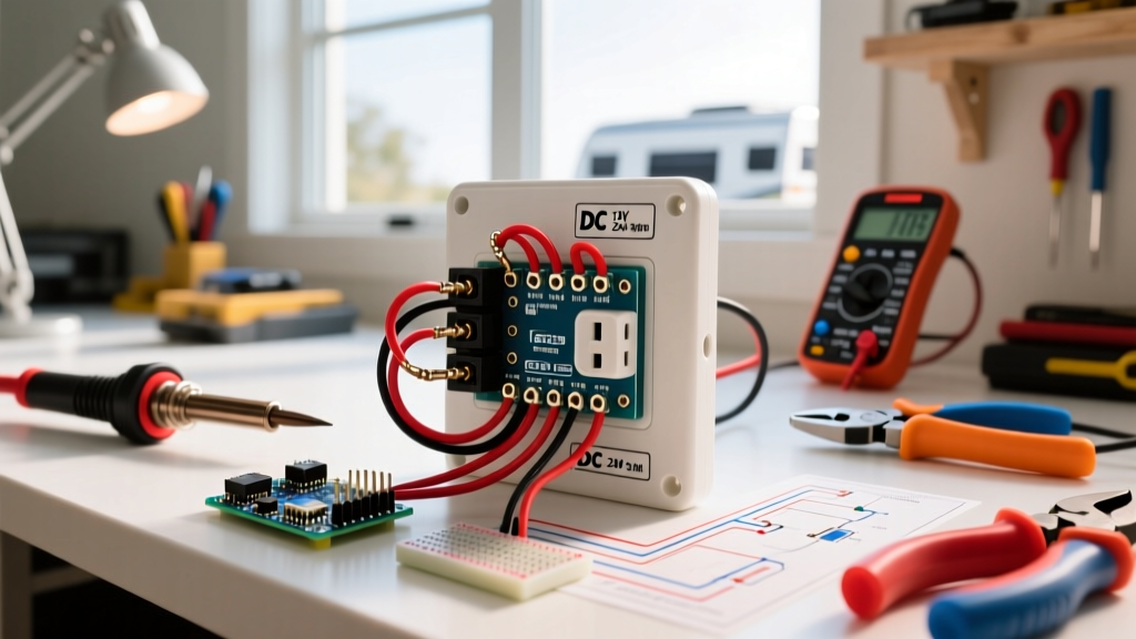
To ensure a professional-grade installation that passes local electrical inspections, gather the following specific tools and materials:
- Outlet Module: 16A 3-pin socket with ISI mark (e.g., Anchor Roma, Havells Crabtree, or Legrand Arteor). Ensure the backplate is polycarbonate or ceramic for high-heat applications.
- Conductor: 2.5 sq mm FRLS (Flame Retardant Low Smoke) multi-strand copper wire.
- Testing Equipment: Non-Contact Voltage Tester (NCVT) and a digital multimeter.
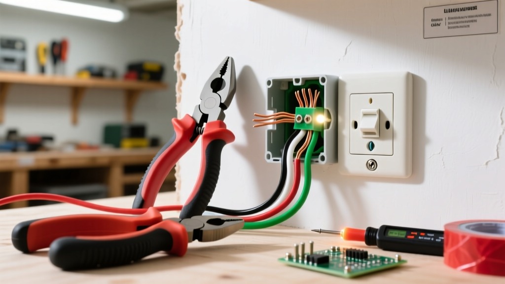
- Hand Tools: Automatic wire stripper (calibrated for 2.5 sq mm), insulated Phillips #2 screwdriver, and a flathead terminal screwdriver.
- Consumables: Insulation tape, cable ferrules (optional but recommended for multi-strand termination).
Pre-Installation Safety and Circuit Isolation
CRITICAL SAFETY WARNING: Never assume a circuit is dead based solely on the wall switch position. In many older Indian buildings, switches may only isolate the Phase (Live) wire, leaving the Neutral energized or floating. Always isolate at the Distribution Board (DB).
- Isolate the MCB: Locate the main Distribution Board and switch off the specific MCB controlling the room or appliance circuit. If unsure, switch off the Main Isolator.
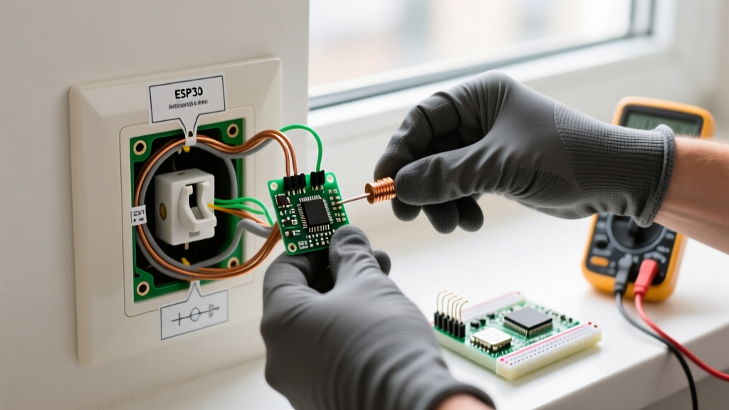
- Verify Zero Potential: Insert the NCVT into the existing outlet slots. The tester must remain completely dark and silent. Follow up with a multimeter set to AC Voltage (V~), measuring Phase-to-Neutral, Phase-to-Earth, and Neutral-to-Earth. All readings must be 0V.
- Lockout/Tagout: If you are working in a shared residential or commercial space, place a physical lock or a prominent warning tag on the DB to prevent accidental re-energization.
Step-by-Step Wiring Procedure
Step 1: Wire Preparation and Stripping
Using your automatic wire stripper, remove exactly 12mm to 15mm of the outer PVC insulation from the Phase, Neutral, and Earth wires. Do not use a utility knife, as nicking the copper strands reduces the cross-sectional area and creates localized hot spots under heavy 16A loads. If using multi-strand wire, twist the exposed strands tightly or, preferably, crimp a 2.5 sq mm bootlace ferrule to prevent strand splaying inside the terminal block.
Step 2: Identify and Adapt to Indian Color Codes
India is currently in a transitional phase regarding wiring color codes, harmonizing with IEC 60446 standards. You must identify the era of your building's wiring:
- Legacy Wiring (Pre-2010s): Red (Phase/Live), Black (Neutral), Green (Earth).
- Modern Wiring (Current IS/IEC Standard): Brown (Phase/Live), Blue (Neutral), Green-Yellow striped (Earth).
Note: For comprehensive details on global and Indian color code transitions, refer to the wiring guides at Electrical Technology.
Step 3: Terminate the Earth (E) Connection First
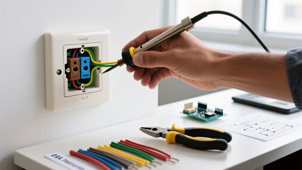
Always connect the Earth wire to the top, largest diameter terminal first. This is a critical safety protocol. If the Earth wire is slightly longer than the Phase/Neutral wires, it ensures that in the event of physical cable strain, the grounding connection is the last to break. Insert the Green (or Green/Yellow) wire into the terminal marked 'E' or with the earth symbol (⏚). Tighten the screw to approximately 0.5 Nm. Ensure no bare copper is exposed outside the terminal housing.
Step 4: Terminate Phase (L) and Neutral (N)
Connect the Phase (Red/Brown) wire to the terminal marked 'L' (Line/Live). Connect the Neutral (Black/Blue) wire to the terminal marked 'N'. In India, it is standard practice for the Phase wire to be routed to the right-hand pin and the Neutral to the left-hand pin when facing the socket, with Earth at the top. Ensure the wire insulation sits flush against the terminal block without being pinched by the tightening screw.
Step 5: Mounting and Dressing the Wires
Carefully fold the wires into the backbox (concealed metal or PVC box). Avoid sharp 90-degree bends which can damage internal insulation over time. Use a spirit level to ensure the mounting plate is perfectly horizontal. Drive the mounting screws into the backbox lugs. Pro-Tip: Do not over-torque the faceplate screws on polycarbonate modules (like the Anchor Roma series), as this can warp the faceplate and cause the internal brass contacts to misalign, leading to poor plug insertion and arcing.
Upgrading a 5A Circuit to a 16A India Electrical Outlet
A common DIY mistake in India is replacing a 5A (Type D) socket with a 16A (Type M) socket to accommodate a new appliance plug, without upgrading the underlying infrastructure. This is extremely hazardous. If you are installing a 16A outlet, you must verify the following:
- Wire Gauge: The concealed wiring must be at least 2.5 sq mm. If the existing wire is 1.5 sq mm, you must pull new 2.5 sq mm conductors through the conduit.
- MCB Rating: The circuit breaker protecting this line must be upgraded from a C10 to a C20 MCB. However, ensure the main DB busbar and upstream wiring can handle the cumulative load increase.
- Earth Continuity: Heavy appliances require a robust earth path. Use an earth resistance tester to verify the socket's earth pin reads less than 1.0 Ohm back to the main earth pit. For more on statutory earthing requirements, consult the Bureau of Indian Standards (BIS) documentation on IS 3043 (Code of practice for earthing).
Common Failure Modes and Troubleshooting
Even with correct installation, specific environmental and grid-related factors in India can cause outlet failures. Here is how to diagnose them:
1. Melted Faceplates or Discoloration
Cause: Loose terminal connections causing high contact resistance, or running a continuous 14A+ load on a socket rated for 16A but manufactured with sub-standard brass thickness.
Fix: Replace the socket with a premium brand featuring thick phosphor-brass contacts. Re-strip and re-torque the wires. Consider hardwiring the appliance via a 20A DP (Double Pole) switch for continuous heavy loads like geysers.
2. NCVT Glows on Neutral Terminal
Cause: A "floating neutral" or a broken neutral connection upstream in the distribution board. In a 3-phase Indian residential setup, a lost neutral can cause severe voltage imbalances, pushing up to 400V into single-phase 230V outlets, instantly destroying connected electronics.
Fix: Immediately shut off the main breaker. Inspect the neutral busbar in the DB for loose screws or burnt links. Do not use the outlet until the neutral continuity is restored and verified with a multimeter.
3. Appliance Trips the GFCI / RCCB
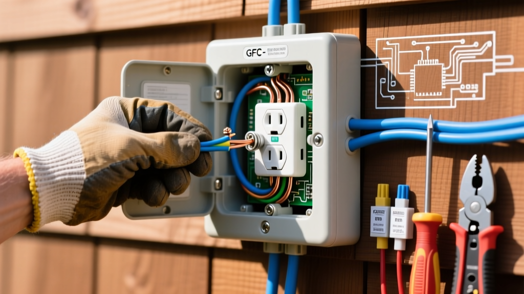
Cause: Modern Indian homes are increasingly equipped with RCCBs (Residual Current Circuit Breakers). If plugging in an appliance trips the RCCB, it indicates leakage current to the earth wire, often due to degraded appliance insulation or moisture ingress in the outlet backbox (common in coastal cities like Chennai or Mumbai).
Fix: Test the outlet's insulation resistance using a Megger (set to 500V DC). Ensure the backbox is sealed against damp walls using silicone caulk around the faceplate edges.
Final Verification and Energization
Once the India electrical outlet is physically secured and all connections are verified, remove your lockout tag and switch the MCB back to the 'ON' position. Use a multimeter to measure the voltage between Phase and Neutral; it should read between 220V and 240V. Finally, plug in a high-wattage resistive load (like a 2kW room heater) for 15 minutes. Monitor the faceplate temperature with an infrared thermometer; it should not exceed ambient room temperature by more than 15°C. If the outlet remains cool and the MCB holds, your installation is complete, safe, and fully compliant with Indian electrical standards.