
Why the Built-In Test Button is Not Enough
When evaluating the safety of a wet-location or kitchen receptacle, many homeowners and novice electricians rely solely on the red and black buttons on the faceplate. While pressing the "TEST" button verifies that the internal sensor coil and tripping mechanism are mechanically functional, it does absolutely nothing to verify the integrity of the electrical wiring GFCI outlet connections behind the drywall. According to the Consumer Product Safety Commission (CPSC), GFCIs prevent over 50% of household electrocutions, but only if the line, load, neutral, and ground conductors are terminated correctly. A GFCI wired with a reversed line/load or an open neutral will still provide power to downstream devices and may even pass a basic plug-in tester, yet it will fail to trip during an actual ground fault event. This inspection and testing guide outlines the professional methodology for verifying GFCI circuits from the junction box to the final receptacle faceplate.
Pre-Installation Inspection: Box Fill and Conductor Routing
Before terminating a single wire, an inspection of the electrical box is mandatory. Modern GFCI receptacles, such as the Leviton SmartlockPro 8200-W or the Eaton GFR83, feature massive internal electronics that protrude up to 1.75 inches into the junction box. Attempting to force these devices into a standard-depth 16-cubic-inch box often results in pinched neutral wires, crushed ground pigtails, or cracked device yokes.
Calculating Box Fill for Deep GFCI Devices
The National Electrical Code (NEC) Article 314.16 dictates strict box fill calculations. When inspecting the wiring preparation for a 120V, 20-Amp GFCI circuit utilizing 12 AWG THHN or Romex, use the following multiplier: 2.25 cubic inches per conductor.
- Incoming Hot and Neutral (12/2): 2 conductors × 2.25 = 4.5 cu in.
- Outgoing Hot and Neutral (Downstream 12/2): 2 conductors × 2.25 = 4.5 cu in.
- Equipment Grounding Conductors (All): 1 allowance × 2.25 = 2.25 cu in.
- Internal Cable Clamps (If present): 1 allowance × 2.25 = 2.25 cu in.
- The GFCI Device Itself: 2 allowances × 2.25 = 4.5 cu in.
Total Minimum Required Volume: 18.0 cubic inches. However, because of the physical depth of the GFCI chassis, professional inspectors mandate the use of "deep" single-gang boxes (minimum 22.5 cubic inches, such as the Carlon B120R-UPC) to prevent wire insulation abrasion against the metal mounting yoke or the printed circuit board on the back of the receptacle.
Post-Installation Testing Matrix: Tools and Expected Results
Once the electrical wiring GFCI outlet is terminated and energized, a multi-tiered testing approach is required. Relying on a $10 plug-in tester is insufficient for diagnosing complex wiring faults. Below is the professional testing matrix.
| Testing Tool | Model Example | Primary Diagnostic Function | Limitations & Edge Cases | Avg. Cost (2026) |
|---|---|---|---|---|
| Receptacle Tester | Klein Tools RT250 | Verifies basic wiring sequence (Hot/Neutral/Ground presence) and trips the GFCI via a simulated ground fault current. | Cannot detect bootleg grounds, high-resistance neutrals, or line/load reversals if downstream power is present. | $35 - $45 |
| True RMS Multimeter | Fluke 117 | Measures exact voltage differentials between Hot-Neutral, Hot-Ground, and Neutral-Ground to identify phantom voltages and reversed polarity. | Requires manual interpretation of voltage drops; does not automatically trip the internal GFCI coil. | $190 - $220 |
| Built-In Test Button | N/A (On Device) | Injects a known current imbalance across the internal toroidal sensor coil to verify mechanical tripping action. | Does NOT verify that the equipment grounding conductor is actually connected to the main panel ground bus. | N/A |
Advanced Multimeter Diagnostics for Edge Cases
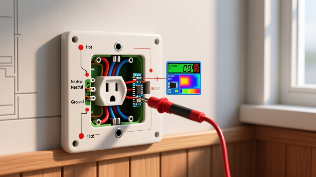
To truly verify the integrity of the circuit, you must use a True RMS multimeter to measure voltage differentials. Set your multimeter to AC Voltage (V~) and perform the following three measurements at the GFCI faceplate and at the furthest downstream receptacle protected by the GFCI's LOAD terminals.
Pro-Tip: When testing downstream receptacles on the LOAD side of a GFCI, a standard plug-in tester might show "Correct" even if the neutral and ground are bonded at the downstream receptacle. The multimeter Neutral-to-Ground test is the only way to catch this dangerous fault.
- Hot to Neutral (Expected: 118V - 122V): Confirms the circuit is energized and the neutral path back to the panel is intact. If this reads 0V but Hot-to-Ground reads 120V, you have an open neutral.
- Hot to Ground (Expected: 118V - 122V): Confirms the equipment grounding conductor is continuous back to the panel's ground bus. If this reads 0V, the GFCI lacks a true ground path (though it will still trip on a fault, the chassis of plugged-in appliances may become energized prior to the trip threshold).
- Neutral to Ground (Expected: 0V - 2V): This is the most critical inspection metric. Under normal load, a slight voltage drop (less than 2V) is acceptable. If you read 120V between Neutral and Ground, your hot and neutral are reversed. If you read exactly 0.0V under heavy load, suspect an illegal neutral-ground bond (a "bootleg ground") somewhere downstream, which bypasses the GFCI's sensing coil and creates a severe shock hazard.
Common Failure Modes: MWBCs and Shared Neutrals
One of the most frequent causes of immediate, unexplainable GFCI tripping during inspection occurs on Multi-Wire Branch Circuits (MWBCs). An MWBC uses two hot wires (on opposite phases) sharing a single neutral wire to supply 240V of total potential across two 120V circuits.
If you wire a GFCI onto an MWBC and connect the shared neutral to the GFCI's LINE neutral terminal, the GFCI will trip the moment any load is applied to the second, non-GFCI circuit. The GFCI's internal toroidal coil monitors the exact current returning on its specific neutral wire. If current from the second hot leg returns through the GFCI's neutral, the coil detects an imbalance and trips.
The Correction: You must pigtail the neutral in the junction box before it enters the GFCI's LINE terminal, ensuring the GFCI only "sees" the neutral current associated with its own hot conductor. Alternatively, upgrade the circuit to a 2-pole GFCI breaker in the main panel and use standard receptacles in the field.
NEC Compliance and Replacement Triggers
The National Fire Protection Association (NFPA) continuously expands GFCI mandates in the NEC. As of the current code cycle, GFCI protection is required for all 125-volt, single-phase, 15- and 20-ampere receptacles installed in dwelling unit kitchens, bathrooms, garages, accessory buildings, crawl spaces, unfinished basements, and outdoor areas. Furthermore, the Electrical Safety Foundation International (ESFI) recommends replacing any GFCI receptacle that is older than 10 years, or any unit that fails to trip during a monthly manual test.
When inspecting older homes, look for "Line/Load Reversal" on legacy installations. Older, non-self-testing GFCIs would still function and provide power if the incoming line wires were accidentally connected to the LOAD terminals. Modern smart GFCIs (like the Leviton SmartlockPro series) feature internal microprocessors that actively block power to the faceplate if a line/load reversal is detected, forcing the electrician to correct the wiring before the device can be used. Always verify the presence of this self-diagnostic feature during a 2026-era electrical inspection.
Final Inspection Checklist
- [ ] Junction box meets minimum 22.5 cubic inch depth requirement.
- [ ] Wire strippers used to exact depth; no exposed copper outside terminal clamps.
- [ ] Torque screwdriver used to tighten terminal screws to manufacturer spec (typically 14-16 in-lbs).
- [ ] Klein RT250 (or equivalent) confirms correct wiring sequence and trips the device.
- [ ] Fluke 117 confirms Neutral-to-Ground voltage is under 2V at the furthest downstream receptacle.
- [ ] GFCI faceplate sits flush with no gaps, and weather-resistant (WR) cover is installed if in a damp/wet location.