
Decoding the Wiring Diagram for GFCI and Light Switch Configurations
For DIYers and beginner electricians, searching for a wiring diagram for GFCI and light switch combinations often leads to confusion. The root of this confusion lies in a single question: Should the GFCI receptacle protect the downstream light switch, or should they operate independently? According to the National Fire Protection Association (NFPA), Ground Fault Circuit Interrupter (GFCI) protection is mandated in wet or damp locations like bathrooms, kitchens, and garages. However, the National Electrical Code (NEC) does not strictly require a standard vanity light switch to be on the GFCI's protected load circuit unless local amendments dictate otherwise.
Understanding how to read and execute the correct wiring diagram for your specific scenario is critical for both safety and code compliance. In this 2026 updated guide, we will break down the exact wiring methodologies, required torque specifications, and edge-case troubleshooting for combining a GFCI outlet (like the industry-standard Leviton GFNT1-W SmartLockPro) with a standard single-pole toggle or rocker switch in a dual-gang box.
The Core Dilemma: Protected vs. Independent Circuits
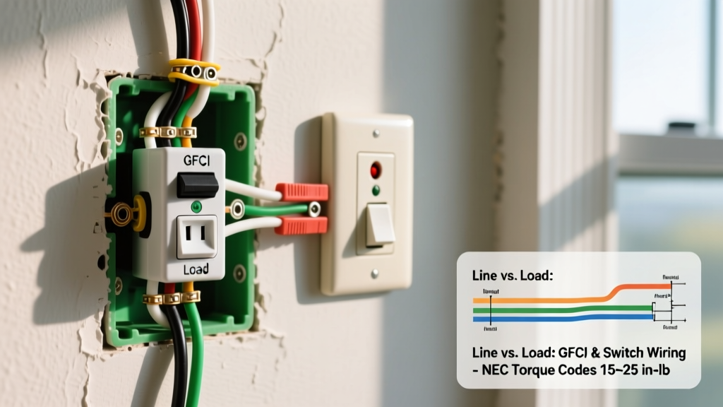
Before stripping any wires, you must determine which of the two standard wiring diagrams applies to your project. The physical wiring changes drastically based on whether you utilize the GFCI's "LOAD" terminals.
| Configuration | Wiring Method | Behavior During GFCI Trip | Best Use Case |
|---|---|---|---|
| Scenario A: Downstream Protection | Power into GFCI LINE; Switch wired to GFCI LOAD. | Light switch loses power; lights turn off. | Bathroom exhaust fans or outdoor lighting where wet-location shock hazard exists. |
| Scenario B: Independent Operation | Power pigtails to both GFCI LINE and Switch simultaneously. | Light switch remains ON; only the outlet loses power. | Bathroom vanity lights, kitchen under-cabinet lighting, or general room illumination. |
Required Tools and 2026 Material Costs
Working with 15-amp (14 AWG) or 20-amp (12 AWG) circuits requires precision. The U.S. Consumer Product Safety Commission (CPSC) notes that improper terminal connections are a leading cause of residential electrical fires. To meet modern NEC 110.14(D) torque requirements, you must use calibrated tools.
- GFCI Receptacle: Leviton 20A SmartLockPro (Model GFTR2-W) or Eaton Wiring Devices. Cost: $22 - $30.
- Single-Pole Switch: Leviton Decora Rocker (Model 5601-W). Cost: $3 - $6.
- Wire Strippers: Klein Tools 11063W (for 10-20 AWG). Cost: $28.
- Torque Screwdriver: CDI Torque 401SM (set to 14 in-lbs for standard receptacle terminals). Cost: $45 - $65.
- Wire Nuts/Connectors: Ideal In-Sure push-in connectors or standard copper crimp sleeves. Cost: $8 per box.
- Non-Contact Voltage Tester: Fluke 2AC-II. Cost: $35.
Scenario A: Wiring Diagram Where GFCI Protects the Light Switch
Use this diagram when the light switch controls a fixture in a wet zone (e.g., an outdoor patio light or a shower exhaust fan) and requires ground-fault protection.
Step 1: Identify Line and Load
Turn off the breaker and verify zero voltage with your Fluke tester. In the wall box, you will typically find two cables: one bringing power from the panel (Line) and one continuing to the next device or light fixture (Load). Use a temporary power-on test with a pigtail and voltage tester before killing the breaker to definitively identify the Line (hot) cable.
Step 2: Wire the GFCI LINE Terminals
Connect the bare copper ground wires together with a pigtail to the green grounding screw on the GFCI. Strip exactly 5/8" of insulation from the black (hot) and white (neutral) wires of the incoming power cable. Connect the incoming black wire to the brass LINE screw and the incoming white wire to the silver LINE screw. Tighten to 14 in-lbs using your torque screwdriver.
Step 3: Wire the Light Switch to the LOAD Terminals
Take the black wire from the outgoing cable (heading to the light fixture) and connect it to one of the brass screws on your standard single-pole light switch. Then, run a short black jumper wire (pigtail) from the second brass screw on the light switch directly to the brass LOAD terminal on the GFCI. Finally, connect the outgoing white neutral wire directly to the silver LOAD terminal on the GFCI.
Expert Warning: Never connect the incoming power to the LOAD terminals. According to Underwriters Laboratories (UL) testing protocols, reverse line/load wiring will leave the outlet energized but disable the internal ground-fault trip mechanism, creating a lethal shock hazard.
Scenario B: Wiring Diagram for Independent Operation (Pigtailing)
This is the most common residential configuration. The GFCI protects the receptacle itself, but the vanity mirror light or ceiling fan remains powered even if the GFCI trips due to a plugged-in hair dryer fault.
Step 1: Create the Hot and Neutral Pigtails
Instead of feeding power through the GFCI, we will split the incoming power. Cut two 6-inch pieces of 12 AWG (or 14 AWG, matching your circuit) black wire, and one 6-inch piece of white wire. Using wire nuts or push-in connectors, join the incoming black wire, the outgoing black wire (if feeding downstream), and your two black pigtails together. Repeat this process for the white neutral wires.
Step 2: Connect the GFCI
Take one black pigtail and connect it to the brass LINE screw on the GFCI. Take the single white pigtail and connect it to the silver LINE screw. Leave the LOAD terminals completely empty and cover them with the yellow warning tape provided by the manufacturer.
Step 3: Connect the Light Switch
Take the second black pigtail and connect it to one of the brass terminal screws on the single-pole light switch. Connect the black wire leading up to your light fixture to the other brass screw on the switch. The light switch does not require a neutral connection unless you are installing a smart switch (like a Lutron Caseta), in which case you would add a third white pigtail from your neutral bundle to the switch's neutral terminal.
Edge Cases and Advanced Troubleshooting
Even with a perfect wiring diagram for GFCI and light switch setups, modern electrical systems present unique challenges that beginner tutorials often ignore.
1. Phantom Tripping from LED Drivers
If your GFCI trips randomly when the light switch is turned on, the culprit is likely the LED fixture. Cheap LED drivers leak a small amount of capacitive current to the ground wire. Over time, or during inrush current, this leakage exceeds the GFCI's 5mA threshold. Fix: Upgrade to UL-listed, low-leakage LED drivers, or install a 0.1µF snubber capacitor across the switch legs to absorb the inductive spike.
2. Multi-Wire Branch Circuits (MWBC)
If your box contains a red wire, a black wire, and a shared white neutral, you are dealing with an MWBC (two 120V circuits sharing one neutral). You cannot wire a standard GFCI on an MWBC without a 2-pole handle-tied breaker. If you attempt to pigtail the shared neutral to a GFCI, the unequal current return will immediately trip the device. You must separate the neutrals or use a specialized 2-pole GFCI breaker in the main panel instead of a receptacle-level GFCI.
3. Overcrowded Dual-Gang Boxes
GFCI devices are significantly deeper than standard switches (often 1.5 to 1.75 inches deep). If you are retrofitting an older home with shallow 1.5-inch total depth boxes, the wires will crush against the back of the device, risking short circuits. You must upgrade to a deep 2-gang "old work" box (minimum 3.5 inches deep, 34 cubic inches volume) to accommodate the bulk of 12/2 Romex and the GFCI chassis.
Frequently Asked Questions
Can I wire a dimmer switch to the LOAD side of a GFCI?
Yes, but it is generally discouraged for indoor lighting. If the GFCI trips, the dimmer loses power and will reset to its default state (usually 100% brightness) when power is restored, ruining your preset lighting levels. Use the independent pigtailing method (Scenario B) for dimmers.
Does the light switch need to be grounded?
Yes. NEC Article 404.9(B) requires all snap switches to be effectively grounded. Even if you are using a plastic faceplate, the metal yoke of the switch must be connected to the equipment grounding conductor (bare copper or green wire) via the green grounding screw.
Why does my GFCI trip immediately when I plug in a device, but the light stays on?
This confirms you wired the circuit using Scenario B (Independent Operation). The GFCI is detecting a ground fault in the appliance you just plugged in (e.g., a frayed cord on a power tool or a faulty heating element in a hair dryer). The switch remains on because it is wired upstream of the GFCI's internal trip relay.