
The Anatomy of a Four Outlet Electrical Box Setup
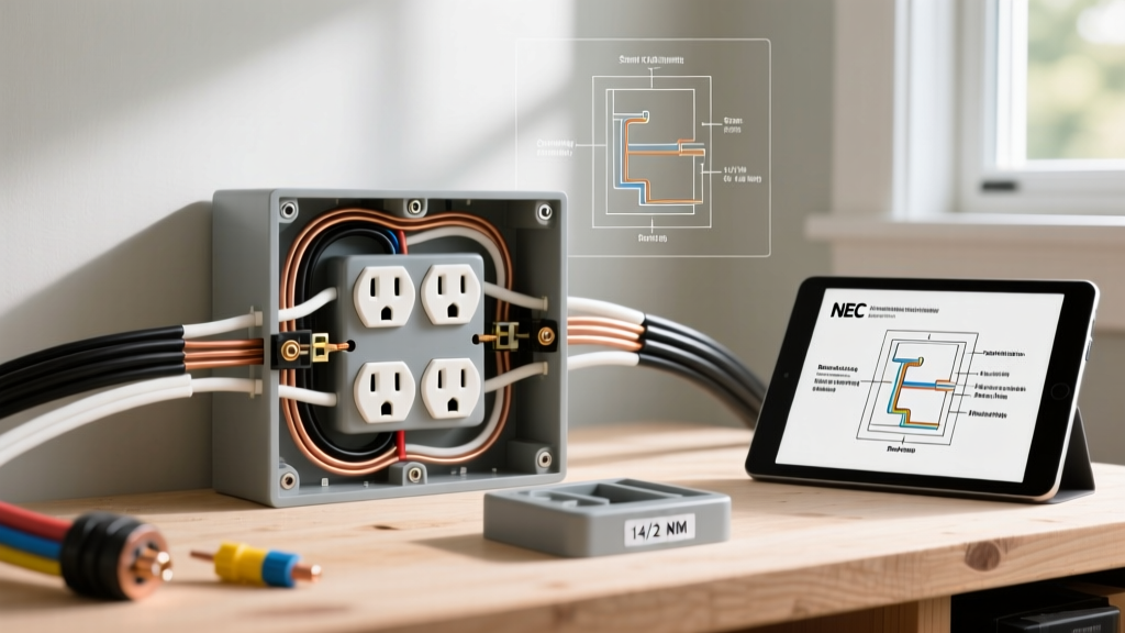
Designing a dedicated workspace, kitchen island, or home entertainment center often requires high-density power access. Installing a four outlet electrical box (a 4-gang configuration) provides eight total receptacle slots, but it introduces significant wiring complexity and strict National Electrical Code (NEC) compliance hurdles. Unlike standard single or double-gang setups, a 4-gang configuration demands rigorous attention to box fill volume, thermal dissipation, and circuit load balancing.
This wiring diagram reference and installation guide breaks down the exact methodologies for wiring four duplex receptacles in a single enclosure, referencing the latest NEC 2023/2026 adoption cycles and industry-standard torque specifications.
Choosing the Right 4-Gang Enclosure
The most common point of failure in multi-receptacle installations is selecting an enclosure with insufficient cubic inch capacity. The NEC strictly regulates the internal volume required to prevent wire insulation damage and overheating. Below is a comparison of standard 4-gang boxes available in 2026, highlighting their suitability for high-density wiring.
| Box Model / Type | Material | Volume (Cubic Inches) | Best Use Case | Avg. Price (2026) |
|---|---|---|---|---|
| Carlon B420R (Nail-On) | Non-Metallic (PVC) | 68.0 cu in | New construction, 12 AWG or 14 AWG Romex | $14.50 |
| Raco 574 (Masonry/Switch) | Galvanized Steel | 42.0 cu in | 14 AWG only; fails NEC box fill for 12 AWG | $18.00 |
| Raco 187 (4-11/16" Square) | Steel + 4-Gang Mud Ring | 42.0 + 21.0 = 63.0 cu in | Retrofits, commercial, EMT conduit, 12 AWG | $22.00 |
NEC Box Fill Calculations: The Math That Prevents Fires
According to NFPA 70 (NEC) Article 314.16, you must calculate the total volume allowances for every conductor, device, and clamp inside the box. Let us run a real-world calculation for a four outlet electrical box wired with 12/2 NM-B (Romex) on a 20-amp circuit.
12 AWG Box Fill Breakdown (2.25 cu in per wire)
- Current-Carrying Conductors: 4 cables entering (4 hots, 4 neutrals) = 8 wires.
- Device Yokes: 4 receptacles. Each device counts as 2 conductors based on the largest wire connected (12 AWG) = 8 wires.
- Equipment Grounding: All bare copper grounds combined count as 1 conductor = 1 wire.
- Cable Clamps: Internal clamps count as 1 conductor = 1 wire.
- Total Conductor Count: 18 wires.
Calculation: 18 wires × 2.25 cubic inches (for 12 AWG) = 40.5 cubic inches minimum required.
Expert Insight: This is why the 42.0 cu in Raco 574 metallic box is dangerously close to the limit and leaves zero room for error or future modifications. Always opt for a 68.0 cu in non-metallic box or a deep steel box with a plaster ring for 12 AWG configurations.
Wiring Topologies: Daisy-Chain vs. Pigtailing
When reviewing a four outlet electrical box wiring diagram, you must choose how to distribute power across the four duplex receptacles. There are two primary methods, but only one is recommended for high-draw environments.
Topology A: The Daisy-Chain (Line-to-Load)
Power enters Receptacle 1, and a second set of wires jumps from Receptacle 1 to Receptacle 2, continuing down the line. Warning: If a neutral wire disconnects at Receptacle 2, all downstream outlets (3 and 4) will lose their neutral return path, potentially causing severe voltage imbalances and destroying connected electronics. Furthermore, passing 20A of continuous load through the internal brass yoke of a 15A or 20A receptacle generates excessive heat.
Topology B: Pigtailing (The Professional Standard)
All four hot wires and all four neutral wires are joined in the back of the box with a single incoming feed wire using a lever-nut connector (e.g., WAGO 221-615). A short 6-inch "pigtail" wire runs from the connector to each individual receptacle.
- Pros: Complete circuit independence; if one receptacle fails, the others remain powered. Reduces thermal stress on device yokes.
- Cons: Requires more internal box volume (which we accounted for in our 68 cu in box selection).
Step-by-Step Wiring Execution Guide
Follow this precise sequence to ensure your four outlet electrical box meets the rigorous standards expected by local inspectors and the Electrical Safety Foundation International (ESFI).
- Prepare the Conductors: Using a precision stripper like the Klein Tools 11063W, strip exactly 3/4 inch of insulation from 12 AWG THHN or Romex wires for side-wiring. Do not nick the copper, which creates a micro-fracture and a future hot spot.
- Grounding First: Connect all bare copper grounds. In a metallic box, you must also pigtail a ground to the box itself. Use a green grounding screw (10-32 thread) tapped into the back of the steel enclosure.
- Splice Neutrals and Hots: Use WAGO 221 lever connectors for pigtailing. They are UL-listed, transparent for visual inspection, and vastly superior to twisted wire nuts for solid 12 AWG wire, reducing installer wrist fatigue.
- Terminate at the Receptacles: We recommend the Leviton 5362-W (15A) or Eaton TRSG20 (20A) Tamper-Resistant duplex receptacles. Wrap the wire clockwise around the terminal screw so that tightening the screw pulls the wire loop tighter.
- Apply Calibrated Torque: NEC 110.14(D) mandates the use of a calibrated torque tool. Set your torque screwdriver (e.g., Wiha 60880) to 14 in-lbs for standard side-wire terminal screws. Under-torquing causes arcing; over-torquing strips the brass threads.
- Leave the Tabs Intact: Unless you are splitting a single receptacle for a switched half-hot configuration, never break the brass (hot) or silver (neutral) connecting tabs on the side of the yoke when pigtailing.
Edge Cases, Troubleshooting, and 2026 Code Updates
GFCI and AFCI Protection Requirements
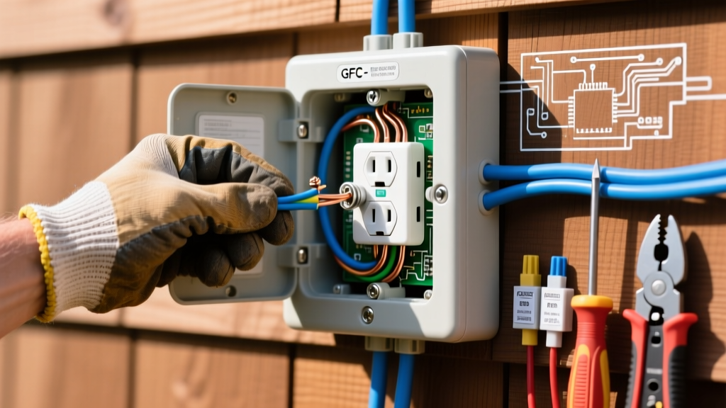
If your four outlet electrical box is located in a kitchen, bathroom, garage, or outdoor patio, NEC mandates Ground Fault Circuit Interrupter (GFCI) protection. Instead of buying four expensive GFCI receptacles, install a single GFCI breaker in the main panel, or wire the first receptacle in the chain as a GFCI and feed the remaining three standard TR receptacles from its "LOAD" terminals. Note: When using the LOAD terminals, you are intentionally daisy-chaining the downstream protection, which is code-compliant and standard practice.
The "Crowded Neutral" Failure Mode
A frequent DIY mistake is shoving all neutral wires into the back of the box without organization, causing them to press against the terminal screws of the hot side. This can lead to a dead short or ground fault. Solution: Fold the neutrals neatly into the top-left corner of the box, and the hots into the bottom-right, keeping the grounding bundle pushed dead-center against the back wall.
Thermal Derating in Enclosed Spaces
If this 4-gang box is being installed inside a sealed custom-built workbench cabinet, be aware of thermal derating. Four receptacles handling simultaneous 12A loads (e.g., power tools, heaters) will generate significant ambient heat. Ensure the cabinet has passive ventilation louvers to keep the internal box temperature below the 60°C (140°F) rating of standard NM-B cable insulation.
Summary Checklist for Inspectors
Before closing up the drywall or attaching the faceplates, verify the following:
- Box fill calculation mathematically verified against installed wire gauge.
- No exposed copper visible outside the terminal yokes (the "no bare copper" rule).
- All terminal screws torqued to manufacturer specifications (typically 14 in-lbs).
- Receptacles are aligned using a cat's paw or alignment tool to prevent faceplate cracking when tightening the 6-32 mounting screws.
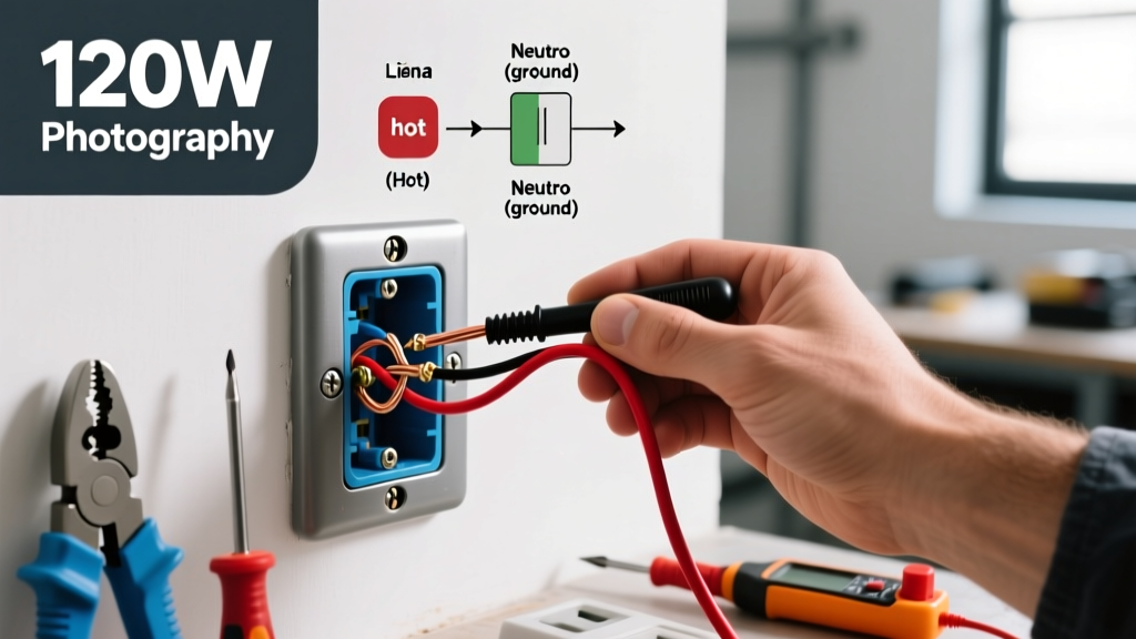
- Circuit is tested with a digital multimeter verifying 120V ± 5% from hot to neutral, and near 0V from neutral to ground.