
Decoding Electrical Outlet Size: Beyond the Faceplate
When DIYers and apprentice electricians search for electrical outlet size, they are usually thinking about the visible faceplate dimensions. However, from a professional wiring diagram and installation perspective, 'size' encompasses three critical dimensions: the physical faceplate footprint, the NEMA receptacle configuration (amperage and slot geometry), and the hidden junction box volume required to safely house the device. Misunderstanding any of these three metrics leads to overcrowded junction boxes, violated NEC bend-radius rules, and potential fire hazards.
In this wiring diagram reference guide, we break down the exact physical measurements, National Electrical Code (NEC) box fill calculations, and the real-world edge cases you will encounter when wiring standard, decorator, GFCI, and smart outlets in 2026.
Physical Dimensions: Faceplates and Yoke Standards
Before pulling wire or drawing a schematic, you must understand the physical envelope of the outlet. The yoke (the metal mounting strap) and the faceplate dictate the wall cutout and the mud ring size.
- Standard Duplex (NEMA 5-15R): The faceplate measures exactly 2.75 inches wide by 4.5 inches tall. The device yoke is approximately 3.28 inches tall, requiring a standard single-gang junction box.
- Decorator / Rocker (Decora-style): The faceplate remains 2.625 inches by 4.5 inches, but the rectangular cutout in the center is larger to accommodate rocker switches and modern smart receptacles.
- Jumbo / Oversized Plates: Measuring 3.5 inches by 5.25 inches, these are not larger outlets, but rather oversized covers used to hide imperfect drywall cuts around standard-sized yokes.
Expert Wiring Tip: When mapping out a multi-gang wiring diagram, always account for the 1.875-inch center-to-center spacing between standard single-gang boxes. If you are installing oversized USB-outlet combos, verify the manufacturer's spec sheet, as some wide-body smart outlets physically overlap if boxes are ganged too tightly.
Amperage Ratings and NEMA Configurations
The 'size' of the receptacle slots dictates the amperage and the wire gauge you must use in your wiring diagram. According to the National Electrical Manufacturers Association (NEMA), standard household outlets fall into two primary categories:
15-Amp Outlets (NEMA 5-15R)
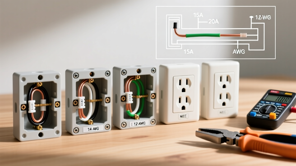
Features two parallel vertical slots (one slightly wider for the neutral) and a U-shaped ground pin. These are rated for 120V and 15 amps. Your wiring diagram must specify 14 AWG copper wire (minimum) protected by a 15A breaker. While 12 AWG wire can be used on a 15A circuit, 14 AWG cannot be used on a 20A circuit.
20-Amp Outlets (NEMA 5-20R)
Visually distinct due to the T-shaped neutral slot, which accepts both 15A and 20A plugs. These are required in kitchens, bathrooms, and garages where high-draw appliances are used. Wiring diagrams for 20A circuits must specify 12 AWG copper wire and a 20A breaker. Note that a 20A circuit can legally utilize standard 15A duplex receptacles (provided there is more than one receptacle on the circuit), but a 20A receptacle can never be installed on a 15A circuit.
The Hidden Size: NEC Box Fill Calculations
The most critical aspect of electrical outlet size from a wiring perspective is the junction box volume. The National Fire Protection Association (NFPA 70 / NEC) outlines strict box fill calculations in Article 314.16. If the physical size of the outlet and its wires exceed the cubic inch capacity of the box, heat builds up, and insulation degrades.
To calculate the required box size for your wiring diagram, assign a cubic inch value to every conductor, clamp, and device yoke based on the wire gauge:
| Wire Gauge (AWG) | Volume per Conductor | Volume for Device Yoke | Volume for All Grounds (Combined) |
|---|---|---|---|
| 14 AWG | 2.0 cu in. | 4.0 cu in. | 2.0 cu in. |
| 12 AWG | 2.25 cu in. | 4.5 cu in. | 2.25 cu in. |
| 10 AWG | 2.5 cu in. | 5.0 cu in. | 2.5 cu in. |
Real-World Calculation Example
Imagine a wiring diagram showing a single 12 AWG cable (1 hot, 1 neutral, 1 ground) entering a box to feed a standard 15A duplex outlet.
- Hot & Neutral: 2 conductors x 2.25 cu in = 4.5 cu in.
- Ground: 1 ground x 2.25 cu in = 2.25 cu in.
- Device Yoke: 2 x 2.25 cu in = 4.5 cu in.
- Total Minimum Box Volume: 11.25 cubic inches.
While an 11.25 cu in box meets the bare NEC math, standard shallow 'old work' boxes are typically 14 cu in, and standard new-construction nail-on boxes are 18 to 22.5 cu in. Always round up to the nearest standard box size to allow for wire bending space.
Edge Cases: GFCI, AFCI, and Smart Outlet Depths
Where DIYers run into severe trouble is ignoring the depth of the outlet body. Standard duplex outlets protrude about 0.9 inches past the yoke. However, modern safety and smart devices are significantly bulkier.
- Standard GFCI Receptacles: Often protrude 1.35 to 1.5 inches. Pigtailing the ground and neutral wires to fit these into a 14 cu in shallow box results in crushed wires and tripped breakers.
- Smart Wi-Fi Outlets (e.g., Leviton Decora Smart): Contain internal relays and Wi-Fi radios, pushing the depth to 1.6 inches or more.
- AFCI/GFCI Dual-Function Outlets: The bulkiest of all, requiring maximum bending radius.
Troubleshooting the 'Shallow Box' Retrofit
According to OSHA electrical safety guidelines, forcing wires into an overcrowded box creates mechanical stress on terminal screws, leading to arcing. If your wiring diagram calls for a GFCI outlet but the existing wall cavity only houses a 14 cu in shallow box, you have three code-compliant solutions:
- Use a Slim-Profile GFCI: Manufacturers like Leviton produce 'slim' GFCIs (e.g., model GFNT1) that shave off crucial millimeters of depth, reducing the overall footprint by up to 25% compared to legacy models.
- Install a Box Extender: A code-compliant plastic or metal ring that mounts over the existing box, adding 0.5 to 1.0 inches of depth and cubic volume.
- Replace the Box: Cut the drywall and install a 22.5 cu in 'deep' single-gang old-work box.
Quick Reference Matrix: Outlet Type to Box Volume
Use this matrix when drafting your wiring diagrams to ensure you specify the correct junction box size for the device type.
| Outlet Type | Typical Device Depth | Min. Recommended Box Volume (12 AWG) | Wiring Diagram Note |
|---|---|---|---|
| Standard 15A Duplex | 0.95" | 14.0 cu in. | Can use push-in back-wire to save space. |
| Decorator 15A/20A | 1.10" | 18.0 cu in. | Requires careful side-wiring; avoid back-stabbing. |
| Standard GFCI | 1.45" | 22.5 cu in. | LINE and LOAD pigtails add to box fill. |
| Slim GFCI (e.g., GFNT1) | 1.15" | 18.0 cu in. | Ideal for shallow retrofit scenarios. |
| Smart Wi-Fi Outlet | 1.65" | 22.5+ cu in. | Requires deep box; neutral wire is mandatory. |
| USB Receptacle Combo | 1.30" | 20.0 cu in. | Heat dissipation requires extra air volume. |
Frequently Asked Questions (FAQ)
Can I install a 20A outlet on a 15A circuit?
No. The NEC strictly prohibits placing a 20A receptacle (NEMA 5-20R) on a 15A circuit. The wiring diagram must match the breaker size, the wire gauge (14 AWG for 15A), and the receptacle rating. Installing a 20A outlet on 14 AWG wire tricks the user into plugging in high-draw appliances, which will overload the wire before the 15A breaker trips.
Do I need a larger box for a GFCI outlet?
Yes, practically speaking. While the NEC box fill math might technically allow a standard GFCI in an 18 cu in box, the physical depth of the GFCI body leaves zero room for the stiff 12 AWG wires to bend. Always specify a 22.5 cu in deep box for GFCI and AFCI receptacles to ensure a safe, stress-free installation.
What size hole saw do I need for outlet faceplates?
Faceplates do not require hole saws; they mount to the junction box via a 6-32 machine screw. However, if you are cutting holes in drywall for the junction box itself, a standard single-gang old-work box requires a rectangular cutout of approximately 2.25 inches by 3.75 inches. Always trace the specific box you are using, as flange sizes vary by manufacturer.
Final Wiring Diagram Takeaways
Understanding electrical outlet size is a three-dimensional exercise. A successful wiring diagram doesn't just show where the black, white, and bare copper wires go; it accounts for the physical cubic inches required to house the device safely. By matching the NEMA configuration to the correct wire gauge, and the device depth to the appropriate junction box volume, you ensure a compliant, long-lasting, and safe electrical installation.