
The Hidden Danger of High-Impedance Testing
If you have ever plugged a standard $10 receptacle tester into a wall, seen the 'Correct' neon lights illuminate, and then later experienced a melted plug when running a space heater, you have encountered the limits of unloaded testing. Standard plug-in testers and digital multimeters (DMMs) are high-impedance devices. They measure voltage potential without drawing meaningful current. While this is fine for verifying the presence of 120V, it completely fails to expose high-resistance connections, failing backstabbed push-in wires, or degraded aluminum splices.
This is where the electrical outlet light bulb test becomes an indispensable diagnostic tool for advanced DIYers and professional electricians. By applying a known resistive load to the circuit, you force the wiring to deliver actual current, instantly revealing voltage drops and arcing faults that unloaded testers simply cannot see.
What Is the Electrical Outlet Light Bulb Test?
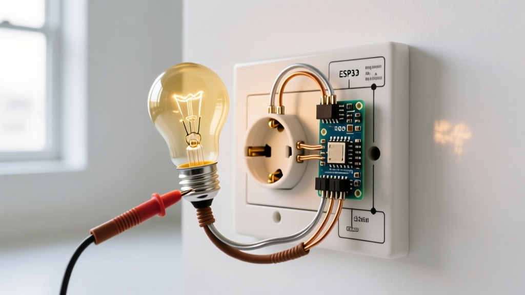
The light bulb load test involves plugging a high-wattage incandescent light bulb into a receptacle to draw a continuous, measurable current (typically 0.5A to 0.8A). According to the National Electrical Code (NFPA 70), branch circuit voltage drop should ideally not exceed 3% to 5% for optimal performance. A degraded connection might show 120V on a multimeter, but when a 60W light bulb demands 0.5 Amps, Ohm's Law (V=IR) dictates that a bad connection with even 10 ohms of resistance will cause a massive voltage drop, dimming the bulb and generating dangerous heat at the fault point.
CRITICAL WARNING: Do not use modern LED bulbs for this test. A standard 9W LED equivalent draws only 0.075 Amps. This micro-load is insufficient to expose high-resistance faults. You must use traditional incandescent or halogen bulbs to achieve the necessary amperage draw.
Tools and Materials Required
To perform this inspection safely and accurately in 2026, you need a specific combination of low-cost components. Do not rely on makeshift exposed-wire rigs.
- Heavy-Duty Plug-In Socket Adapter: Leviton 001-00218 Porcelain Lampholder with 3-prong plug (Approx. $6.50). Avoid cheap plastic adapters; porcelain handles the heat of a 100W bulb safely.
- Incandescent Bulb: 60W or 100W A19 Incandescent (Approx. $3.00). 100W is preferred for longer circuit runs to maximize the load.
- Digital Multimeter (DMM): Any true-RMS meter (e.g., Fluke 117 or Klein Tools MM400) to measure the voltage drop under load.
- Standard 3-Prong Receptacle Tester: For the initial unloaded sequence check (e.g., Gardner Bender GRT-13).
The Load Comparison Matrix
| Testing Method | Impedance / Load | Current Draw | Exposes Backstab Faults? | Avg Cost (2026) |
|---|---|---|---|---|
| Standard Neon Tester | ~0.001W | < 1mA | No | $8 - $12 |
| Digital Multimeter | 0W (10 MΩ High Z) | 0A | No | $40 - $250 |
| 60W Incandescent Bulb | 60W Resistive | 0.5A | Yes | $5 - $9 |
| 100W Incandescent Bulb | 100W Resistive | 0.83A | Yes (Better) | $5 - $9 |
| Dedicated Circuit Analyzer | 15A - 20A Trip | 125A+ (Surge) | Yes (Breaker Trip) | $160 - $220 |
Step-by-Step Inspection Procedure
The Electrical Safety Foundation International (ESFI) emphasizes that electrical diagnostics should always follow a systematic approach to prevent arc flash hazards. Follow these steps precisely.
Step 1: Visual and Physical Pre-Check
Before applying any power or load, inspect the receptacle face. Look for scorch marks, cracked faceplates, or blades that feel loose when inserting a standard plug. If the plug slides in without mechanical resistance, the internal brass contact springs are fatigued, and the receptacle must be replaced regardless of the wiring condition.
Step 2: The Unloaded Baseline Test
- Plug in your standard 3-prong neon tester. Verify the wiring sequence (Hot, Neutral, Ground) is correct.
- Remove the tester and insert your DMM probes into the Hot (short slot) and Neutral (long slot). Record the unloaded voltage. A healthy residential circuit in 2026 typically reads between 118V and 124V.
Step 3: Applying the Light Bulb Load
- Screw your 60W or 100W incandescent bulb into the porcelain plug-in adapter.
- Plug the adapter into the receptacle. The bulb should illuminate instantly and brightly.
- While the bulb is lit, carefully insert your DMM probes into the adjacent duplex receptacle (or use a splitter if testing a single outlet) to measure the Hot-to-Neutral voltage under load.
Step 4: Calculate the Voltage Drop
Subtract the loaded voltage from your baseline unloaded voltage. If your baseline was 122V and the loaded voltage drops to 115V, you have a 7V drop (5.7%). According to NEC guidelines, a drop exceeding 5% on a branch circuit indicates a high-resistance fault that requires immediate remediation.
Diagnosing Failure Modes and Edge Cases
The behavior of the electrical outlet light bulb during the test provides immediate, actionable diagnostic data without ever removing the faceplate.
Symptom: Bulb Glows Dimly or Flickers
Diagnosis: High-resistance series fault. This is almost always caused by a failing 'backstabbed' push-in wire connection on the back of the receptacle, or a loose wire nut in a junction box upstream. The flickering indicates micro-arcing, which generates intense localized heat and is a leading cause of residential electrical fires. As outlined in OSHA's electrical safety guidelines, arcing faults must be eliminated immediately by cutting back the damaged wire and using a side-wire screw terminal or a proper pigtail connection.
Symptom: Bulb Pops or Breaker Trips Instantly
Diagnosis: Overvoltage or dead short. If the bulb flashes brilliantly and pops, the receptacle may be miswired to 240V (common in converted workshop spaces or HVAC closets). If the breaker trips instantly, the hot and neutral may be shorted downstream, or the breaker itself is overly sensitive/failing. Turn off the breaker immediately and do not re-energize until a continuity test is performed with the power off.
Edge Case: Testing GFCI Pass-Through Terminals
GFCI receptacles have 'LINE' and 'LOAD' terminals. While the light bulb test will not trip the GFCI's internal ground-fault sensor (which requires a 5mA leakage to ground), it is the perfect test for the LOAD terminals. Many cheap GFCIs fail internally on the load-side pass-through contacts after years of use. If downstream outlets are dead, but the GFCI itself powers a light bulb brightly, the internal load relay has likely failed, requiring a full GFCI replacement.
When to Upgrade to a Dedicated Circuit Analyzer
While the light bulb test is exceptional for finding resistive faults, it does not test the magnetic trip mechanism of your circuit breaker. If you are inspecting a panel with AFCI/GFCI breakers, or need to verify that a 20A breaker will actually trip under a true 20A fault, you must upgrade to a dedicated load tester like the Ideal SureTest 61-055 or the Amprobe AT-3500. These devices draw 15 to 20 Amps of continuous current and can simulate ground faults, but they cost upwards of $175. For 90% of standard residential receptacle inspections, the $9 light bulb method provides the critical information needed to ensure safe, low-resistance connections.
Frequently Asked Questions
Can I use a halogen work light bulb for this test?
Yes, a 100W to 300W halogen bulb provides an excellent, high-amperage resistive load. However, halogen bulbs generate extreme surface temperatures (often exceeding 400°F). Ensure the porcelain adapter is rated for the wattage, and keep the bulb away from combustible materials during the 30-second test window.
Does this test work on 20-Amp kitchen circuits?
Absolutely. Kitchen circuits often suffer from voltage drop due to long wire runs and heavy continuous loads (microwaves, toasters). Applying a 100W light bulb load to a 20A kitchen receptacle is a safe, effective way to verify the integrity of the 12 AWG wiring and the mechanical grip of the 20A T-blade receptacle contacts.
What if the voltage drops, but the bulb stays bright?
Human eyes are remarkably poor at judging slight changes in incandescent brightness due to the non-linear response of the filament. A 10V drop might only result in a 15% reduction in lumens, which is hard to see in a well-lit room. Always trust the hard data from your digital multimeter over visual estimation.