
The Critical Role of the Electrical Outlet Ground
In modern residential and commercial wiring, the electrical outlet ground is the unsung hero of life safety. While the hot conductor delivers power and the neutral provides the return path for normal current, the equipment grounding conductor (EGC) sits idle—until a catastrophic fault occurs. When a live wire touches a metal appliance chassis or a defective plastic receptacle housing, the ground wire provides a low-impedance path back to the panel. This massive surge of fault current instantly trips the breaker, preventing lethal electric shock and electrical fires.
According to the National Fire Protection Association (NFPA), electrical failures and malfunctions account for tens of thousands of home fires annually. A properly installed and bonded electrical outlet ground is your primary defense against these hazards. As we navigate the 2026 enforcement cycles of the National Electrical Code (NEC), understanding how to test, troubleshoot, and upgrade grounding systems is essential for any DIYer or electrical professional.
Anatomy of a Code-Compliant Grounded Receptacle
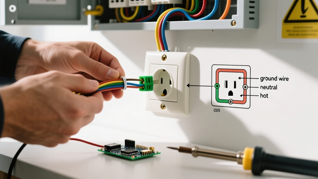
A standard 120-volt, 15-amp or 20-amp grounded receptacle features three distinct terminals:
- Hot (Brass Screw): Connects to the black (or red) insulated wire. Carries 120V from the breaker.
- Neutral (Silver Screw): Connects to the white insulated wire. Completes the circuit back to the neutral bus bar.
- Ground (Green Screw): Connects to the bare copper or green insulated wire. Bonds the receptacle's metal yoke and any plugged-in appliance to the grounding electrode system.
For 15-amp circuits, the NEC mandates a minimum of 14 AWG copper wire, while 20-amp circuits require 12 AWG copper. When wiring the electrical outlet ground to a metal electrical box, NEC Article 250.148 requires that the EGC be secured to the box with a grounding screw or listed grounding clip, and a pigtail must be run to the receptacle's green screw. You cannot rely solely on the receptacle's mounting screws to bond the ground through the metal yoke; a dedicated copper pigtail is mandatory for a reliable, low-impedance fault path.
NEC Grounding and Bonding Requirements
The NEC draws a strict distinction between grounding (connecting to the earth) and bonding (connecting metallic parts together to ensure electrical continuity). Your electrical outlet ground is technically an equipment bonding jumper that ties back to the main panel's neutral-to-ground bond.
CRITICAL SAFETY WARNING: Never create a 'bootleg ground.' This illegal and highly dangerous practice involves installing a jumper wire between the neutral silver screw and the green ground screw on a 3-prong receptacle to fool a tester. If the neutral wire breaks upstream, the metal casing of any plugged-in appliance will become energized at 120V, posing a fatal shock hazard. The Occupational Safety and Health Administration (OSHA) strictly prohibits this configuration in all environments.
How to Test an Electrical Outlet Ground
Verifying the integrity of an electrical outlet ground requires more than just looking at the wires. You must measure the actual impedance and voltage potential. Here is the professional workflow using a Fluke 117 True RMS Multimeter and a Klein Tools RT210 Receptacle Tester.
Step 1: The Receptacle Tester Sweep
Plug the Klein RT210 into the outlet. This device uses a combination of neon lamps to indicate basic wiring faults. While it cannot measure high-impedance grounds, it will instantly flag open grounds, reversed polarity, and hot/neutral swaps.
Step 2: Multimeter Voltage Drop Testing
Set your Fluke 117 to V AC. Insert the probes into the receptacle slots to measure specific voltage relationships:
- Hot to Neutral: Should read between 118V and 122V.
- Hot to Ground: Should read identically to Hot to Neutral (118V - 122V). If this reads 0V, you have an open ground.
- Neutral to Ground: This is the most critical test. It should read less than 2.0V (ideally 0.1V to 0.5V). A reading higher than 2V indicates a high-impedance ground, a shared neutral overload, or a loose neutral connection at the panel.
Troubleshooting Matrix: Tester Light Patterns & Multimeter Readings
| Condition | Klein RT210 Lights | Fluke 117 (Neutral-to-Ground) | Required Action |
|---|---|---|---|
| Correct Wiring | Yellow + Green ON | < 1.0V | None. System is safe and code-compliant. |
| Open Ground | Yellow ON only | 0.0V (No continuity) | Trace EGC back to panel; repair broken copper wire. |
| Bootleg Ground | Yellow + Green ON | 0.0V (but fails load test) | Remove neutral-to-ground jumper; rewire properly. |
| Hot/Neutral Reversed | Red + Yellow ON | ~120V | Swap black and white wires on receptacle terminals. |
| High-Impedance Ground | Yellow + Green ON | > 3.0V | Tighten panel bus bar screws; check for loose pigtails. |
Upgrading Ungrounded (2-Prong) Outlets Safely
Millions of older homes built before the 1960s feature ungrounded 2-prong receptacles. Homeowners often want to upgrade to 3-prong outlets to accommodate modern electronics. Under NEC Article 406.4(D), you have three code-compliant paths to address an ungrounded electrical outlet ground scenario:
Option 1: Run a New Equipment Grounding Conductor
The gold standard is replacing the old 2-wire cloth or knob-and-tube cable with modern 12/2 NM-B (Romex) cable. This provides a dedicated bare copper ground wire all the way back to the panel's ground bus. Expect to pay roughly $0.75 to $1.10 per foot for 12/2 NM-B in 2026, plus drywall repair costs.
Option 2: GFCI Protection (The 'No Equipment Ground' Exception)
If running new cable is structurally impossible, the NEC allows you to replace a 2-prong outlet with a 3-prong receptacle if it is protected by a Ground Fault Circuit Interrupter (GFCI). You must apply the included 'GFCI Protected' and 'No Equipment Ground' stickers to the faceplate. Note: A GFCI does not create a ground; it simply monitors the current imbalance between hot and neutral, tripping in 5 milliseconds if a 4mA to 6mA leak is detected. Surge protectors plugged into these outlets will not function properly, as they require a true EGC to divert transient voltage spikes.
Option 3: Retrofit a Ground Wire Only
NEC 250.134 Exception 1 permits retrofitting a bare copper ground wire to an existing ungrounded circuit, provided the wire is routed back to the same panel and bonded to the ground bus bar or a grounding electrode conductor. This avoids pulling new hot and neutral wires but requires fishing a single 12 AWG bare wire through the walls.
Common Grounding Failure Modes & Edge Cases
Even when an electrical outlet ground appears visually intact, hidden failures can compromise safety:
- Daisy-Chain Breaks: In older wiring, the ground wire was sometimes wrapped around the screw and cut, relying on the downstream outlet to maintain continuity. If a downstream wire is removed, the upstream ground is severed. Always use pigtails with U.S. Consumer Product Safety Commission (CPSC) recommended wire connectors (e.g., Ideal Twister 341) to ensure continuous grounding regardless of downstream device removal.
- Ground Loops in AV Equipment: When multiple devices are plugged into different outlets on different circuits, slight voltage potentials between the ground paths can cause a 60Hz hum in audio systems. This is solved by using isolated ground (IG) receptacles (orange face) in commercial settings, or point-to-point single-circuit wiring in residential home theaters.
- Painted Yokes: Layers of latex paint over the receptacle's metal mounting yoke can insulate it from a metal electrical box, breaking the bonding path. Always scrape paint from the box edges where the yoke makes contact.
Estimated Costs and Tool Requirements (2026 Pricing)
| Item / Tool | Purpose | Estimated Cost |
|---|---|---|
| Fluke 117 True RMS Multimeter | Accurate AC voltage and continuity testing | $210.00 |
| Klein Tools RT210 Tester | Quick visual fault detection and GFCI trip testing | $28.00 |
| Leviton T5320-W (15A TR) | Tamper-Resistant duplex receptacle | $3.50 |
| 12/2 NM-B Cable (250ft roll) | Full circuit rewiring with EGC | $165.00 |
| Ideal Twister 341 Wire Nuts | Secure pigtailing for ground continuity | $12.00 / pack |
Frequently Asked Questions
Can I ground an outlet directly to a metal electrical box?
Yes, but only if the metal box itself is properly grounded via metal conduit (EMT/Rigid) or a continuous armor cable (MC/ACW). You must use a listed green grounding screw (10-32 thread) tapped into the back of the box, attach a bare copper pigtail, and connect the other end to the receptacle's green screw. Relying on the mounting screws alone violates NEC 250.148.
Is it safe to use a 3-prong to 2-prong cheater plug adapter?
No. These 'cheater plugs' are designed with a small wire loop meant to be screwed into the center faceplate screw, assuming the box is grounded. In 99% of older homes with ungrounded 2-prong outlets, the metal box is not grounded, rendering the adapter useless and leaving you with a false sense of security. It also creates a severe trip hazard and violates OSHA workplace safety standards.
Why does my multimeter read 40V between Neutral and Ground?
A reading of 40V (or any significant phantom voltage) between neutral and ground usually indicates a broken or highly resistive neutral connection somewhere upstream, or an induced voltage on an open ground wire. Turn off the breaker immediately. A healthy neutral-to-ground reading under load should never exceed 2V. If you measure 40V, you likely have a floating neutral or an open ground wire acting as an antenna for electromagnetic interference.