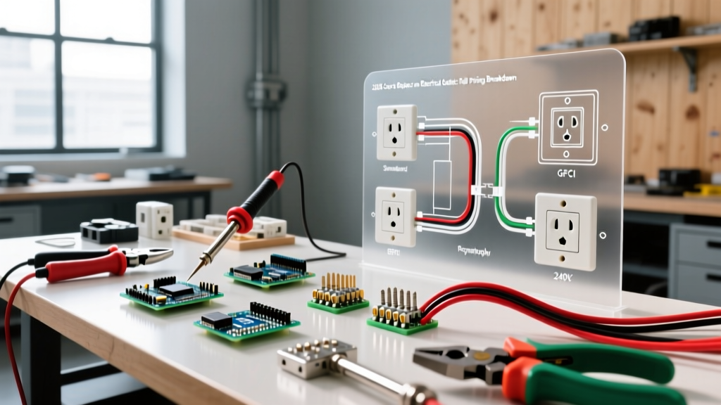

Why Install an Electrical Outlet Floor Box?
In modern open-concept homes and commercial spaces, routing power across large rooms without creating tripping hazards is a persistent challenge. Installing an electrical outlet floor box provides a clean, code-compliant solution for kitchen islands, home office desks, and living room seating areas. As of 2026, the demand for integrated power solutions has surged, with many homeowners opting for pop-up floor receptacles that include 100W USB-C Power Delivery (PD) ports alongside standard 120V AC outlets.
However, unlike standard wall receptacles, floor boxes are subjected to unique mechanical and environmental stresses. They must withstand foot traffic, rolling chairs, vacuum cleaners, and accidental liquid spills. This comprehensive, step-by-step installation guide will walk you through the process for both wood-framed subfloors and concrete slab-on-grade foundations, ensuring your installation is safe, durable, and fully compliant with the National Electrical Code (NEC).
NEC Code Requirements for Floor Receptacles
Before cutting into your floor, it is critical to understand the governing electrical codes. The National Fire Protection Association (NFPA) outlines specific requirements for floor boxes under NEC Article 314.27(B).
NEC Article 314.27(B) Floor Boxes: Floor boxes shall be listed for the purpose and shall be installed in such a way that the floor covering will not be damaged. Boxes listed for use in wet locations must be used where the floor is subject to wet mopping or liquid spills.
Key takeaways for your installation:
- Listing Requirement: You cannot use a standard wall outlet box turned sideways. The box and cover assembly must be UL-listed specifically for floor use.
- Structural Integrity: The box must be securely fastened to the floor structure to prevent it from being pulled out when a cord is yanked.
- Wet Locations: If installing in a kitchen or near an entryway, you must use a wet-location rated cover (e.g., IP54 or higher) to prevent mop water from causing a short circuit.
Tools and Materials Matrix
Selecting the right hardware is half the battle. Below is a comparison of popular 2026 floor box models and the specific tools required for each subfloor type.
| Category | Wood Subfloor | Concrete Slab |
|---|---|---|
| Recommended Box | Carlon E971 Non-Metallic Floor Box ($45-$55) | Leviton 6230N-LG Brass Pop-Up Box ($90-$120) |
| Cutting Tool | Milwaukee 49-56-7250 (4-1/8 inch Hole Saw) | Bosch DC5074 5-inch Diamond Core Bit |
| Fastening | 1-1/2 inch Wood Screws & Construction Adhesive | Tapcon Concrete Anchors & Epoxy Sealant |
| Dust Management | Standard Shop-Vac | HEPA-filtered Dust Extractor (OSHA compliant) |
| Wiring | 12/2 NM-B (Romex) or 12 AWG THHN in Flex | 12 AWG THHN in Rigid or PVC Conduit |
Scenario A: Wood Subfloor Installation (Step-by-Step)
Installing an electrical outlet floor box in a wood-framed floor (typically 3/4-inch plywood or OSB over joists) is the most common residential scenario. This method requires careful joist mapping to avoid structural damage.
Step 1: Locate and Mark the Cutout
Use a high-quality stud finder to locate the floor joists. You must position the floor box entirely within a single joist bay. Mark the center point of your desired outlet location. Place the template provided with your floor box kit over the mark and trace the cut line. For the Carlon E971, this is typically a 4-1/8 inch diameter circle.
Step 2: Drill the Access Hole
Attach the appropriately sized hole saw to your corded drill. Drill a 1/4-inch pilot hole completely through the floor to verify there are no plumbing lines or HVAC ducts directly below. Once verified, use the hole saw to cut the main opening. Apply steady, moderate pressure to prevent splintering the hardwood or laminate surface.
Step 3: Route the Electrical Cable
From the basement or crawlspace below, drill a 3/4-inch hole through the bottom plate or joist to route your 12/2 NM-B cable up into the joist bay. Feed the cable up through the floor opening, leaving at least 12 inches of slack inside the box. Secure the cable to the joist using approved cable staples within 8 inches of the box.
Step 4: Mount the Box and Terminate
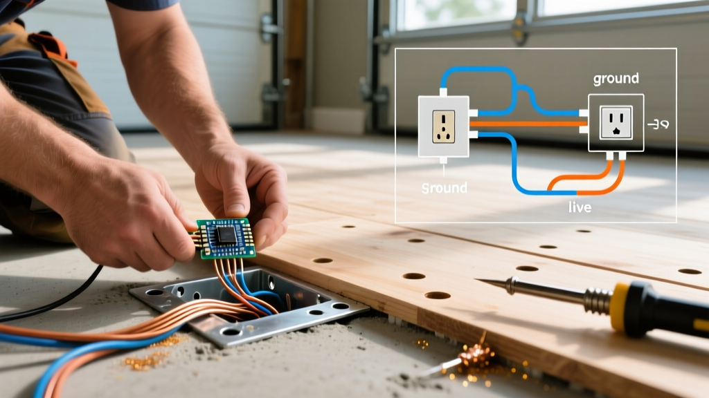
Apply a bead of polyurethane construction adhesive to the mounting flange of the floor box. Drop the box into the hole and secure it using the provided wood screws. Strip the NM-B sheathing, leaving 1/4 inch of insulation intact. Connect the bare ground to the green grounding screw, the white neutral to the silver terminal, and the black hot to the brass terminal. Torque the terminal screws to the manufacturer's specification (usually 12-14 in-lbs) to comply with NEC 110.14(D).
Scenario B: Concrete Slab Installation (Step-by-Step)
Installing an electrical outlet floor box in a concrete slab is significantly more labor-intensive and is typically done during new construction or major renovations. Retrofitting requires core drilling and trenching.
Step 1: Core Drilling the Slab
Mark the cutout using the brass cover plate template. Because concrete drilling generates hazardous silica dust, OSHA Electrical Safety and Health Guidelines mandate the use of water suppression or a HEPA vacuum extraction system. Attach the diamond core bit to a rotary hammer drill with a vacuum shroud. Drill down to a depth of 3-1/2 inches, ensuring you do not sever any post-tension cables or embedded radiant heating tubes.
Step 2: Trenching for Conduit
Using a concrete saw with a diamond blade, cut a shallow trench (1/2 inch deep) from the nearest wall junction box to the floor hole. Lay 1/2-inch PVC or EMT conduit in the trench. Feed your 12 AWG THHN wires (Black, White, Green) through the conduit into the floor box cavity.
Step 3: Setting the Box in Epoxy
Vacuum the core hole completely clean. Mix a two-part structural epoxy and apply it to the sides and bottom of the hole. Press the Leviton 6230N-LG Floor Box into the cavity. Use a torpedo level to ensure the flange is perfectly flush and level with the finished concrete surface. Allow the epoxy to cure for 24 hours before applying any weight.
Step 4: Seal and Terminate
Apply a bead of silicone sealant around the exterior edge of the flange to prevent moisture migration from the concrete. Terminate the THHN wires to a 20A commercial-grade receptacle. Snap the brass pop-up cover plate into place.
Wiring Best Practices and Edge Cases
When wiring an electrical outlet floor receptacle, standard wall-outlet habits can lead to premature failure. Consider the following expert insights:
- Use Commercial-Grade Receptacles: Always use a 20A commercial-specification receptacle (e.g., Leviton 5352) even if you are on a 15A breaker. Commercial receptacles feature thicker brass contacts and deeper termination wells that resist the mechanical shock of foot traffic.
- Pigtail Your Connections: Never use the receptacle's internal push-in back-wire holes, and avoid daisy-chaining the feed-through terminals on floor boxes. Always use wire nuts or Wago 221 connectors to pigtail the incoming and outgoing wires to the receptacle. This ensures that if the receptacle fails, downstream power is not interrupted.
- Strain Relief: For pop-up style boxes, ensure the internal cable management bracket is securely clamped over the NM-B or THHN wires. When the pop-up mechanism is extended, the wires will flex; without proper strain relief, the terminal connections will eventually loosen and arc.
Common Failure Modes and Troubleshooting
Even with a meticulous installation, floor outlets face unique operational hazards. Here is how to diagnose and prevent the most common issues:
1. Breaker Tripping After Mopping
Cause: Liquid ingress into a dry-location rated box. Standard brass flip-covers are not watertight.
Solution: Upgrade to a wet-location floor box cover with a threaded, gasketed screw-down cap (such as the Hubbell SystemOne series). If the GFCI breaker has already tripped, allow the box to dry completely for 48 hours and test the insulation resistance with a megohmmeter before resetting.
2. Receptacle Feels Loose or Wobbly
Cause: The yoke (mounting strap) of the receptacle is not properly supported by the box, causing it to tilt when a plug is inserted or removed.
Solution: Install plastic receptacle shims between the yoke and the box mounting ears. Ensure the mounting screws are tightened evenly. If the drywall or concrete edge is crumbling, use longer 6-32 machine screws with fender washers to distribute the load.
3. USB-C Ports Overheating
Cause: Poor ventilation inside a sealed pop-up box combined with high-draw devices (like gaming laptops) pulling continuous 100W.
Solution: Ensure the floor box is rated for the specific thermal load. In 2026, many manufacturers offer floor boxes with integrated thermal cutoff switches. If your current box lacks this, consider separating the data/USB charging to a dedicated low-voltage floor box adjacent to the high-voltage AC box to improve heat dissipation.
Final Inspection and Safety Check
Before covering the box with furniture, perform a final verification. Use a digital receptacle tester to confirm correct wiring (hot, neutral, and ground). If the circuit requires GFCI protection (mandatory for kitchen islands or within 6 feet of a wet bar sink per NEC 210.8), press the 'Test' button on the GFCI device to ensure it trips correctly. Finally, walk over the closed cover plate in hard-soled shoes to verify it sits flush and does not produce a metallic rattle, which indicates a loose mounting flange. By following these precise steps, your electrical outlet floor installation will provide safe, reliable power for decades.