
The Beginner's Blueprint: Decoding the Double Pole Switch
When upgrading your home's electrical infrastructure in 2026, encountering a double pole switch is a rite of passage. Unlike standard single-pole switches that control a simple 120V lighting circuit from one location, a double pole switch acts as two single-pole switches mechanically linked by a single toggle lever. They are primarily used to control 240V appliances (like baseboard heaters or well pumps) or to simultaneously disconnect both hot legs of a Multi-Wire Branch Circuit (MWBC).
One of the most dangerous beginner mistakes is confusing a double pole switch with a 3-way switch. While both feature four terminal screws (plus ground), their internal mechanics and wiring diagrams are entirely different. This comprehensive tutorial will walk you through the exact wiring diagram for a double pole light switch, ensuring your installation meets current National Electrical Code (NEC) standards.
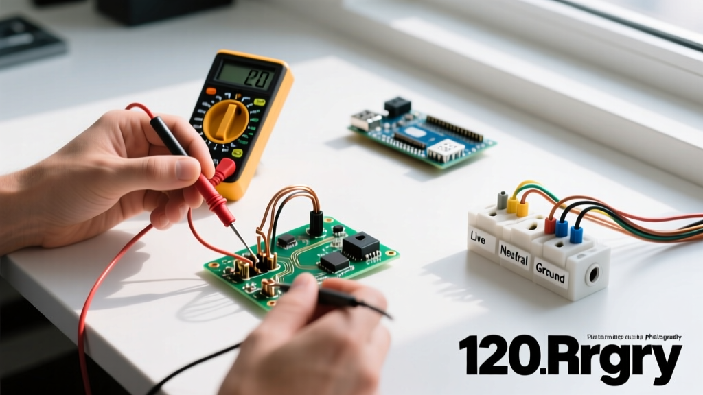
Safety Warning: Working with 240V circuits or MWBCs carries a severe risk of arc flash and electrocution. Always adhere to Lockout/Tagout (LOTO) procedures. According to the Occupational Safety and Health Administration (OSHA), verifying a zero-energy state with a calibrated multimeter is mandatory before touching any bare conductor.
Anatomy of a Double Pole Switch
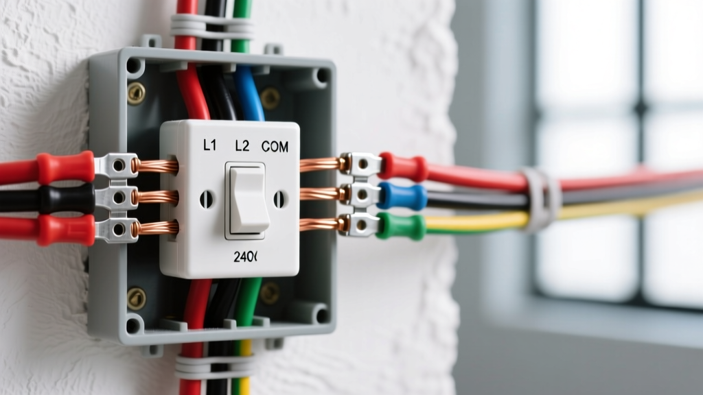
Before we map out the wiring diagram, you must understand the physical anatomy of the device. A standard 20-amp double pole toggle switch (such as the widely available Leviton 3032-2W, retailing around $8.50 in 2026) features:
- Four Brass Terminal Screws: These are the 'Line' and 'Load' connections for the two separate hot circuits. There is no distinction between line and load on a standard double pole switch; either side can accept the incoming power.
- One Green Ground Screw: Connects to the bare copper or green insulated equipment grounding conductor.
- No Neutral Terminal: Neutrals are never switched. They must bypass the switch entirely via a wire nut.
Terminal Mapping Diagram
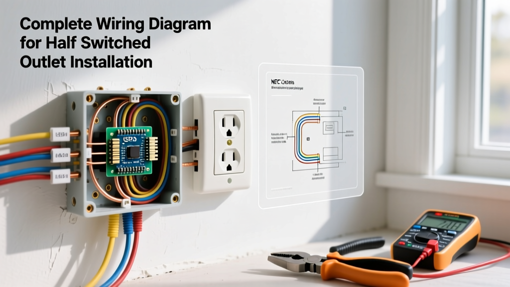
Because text-based guides cannot provide an image, use this structured mapping table as your definitive wiring diagram reference:
| Cable Source | Wire Color | Switch Terminal | Function |
|---|---|---|---|
| Panel (Line 1) | Black (Hot A) | Brass Screw 1 (Top Left) | Incoming 120V Leg 1 |
| Panel (Line 2) | Red (Hot B) | Brass Screw 2 (Top Right) | Incoming 120V Leg 2 |
| Load (Leg 1) | Black (Hot A) | Brass Screw 3 (Bottom Left) | Outgoing to Appliance/Fixture |
| Load (Leg 2) | Red (Hot B) | Brass Screw 4 (Bottom Right) | Outgoing to Appliance/Fixture |
| Ground | Bare / Green | Green Screw | Equipment Grounding |
| Neutral | White | N/A (Bypass) | Wire-nutted together in the box |
The MWBC Factor: Why NEC Mandates Double Pole Switches
In modern residential wiring, you will frequently use a double pole switch to control kitchen or bathroom receptacles wired as a Multi-Wire Branch Circuit. Under NEC Article 210.4(B) (NFPA 70), all ungrounded conductors of an MWBC must be disconnected simultaneously. If you use two separate single-pole switches on an MWBC and only turn one off, the shared neutral wire can still carry the unbalanced return current from the other live leg, creating a lethal shock hazard for anyone working on the circuit. A double pole switch guarantees both hot legs are severed at the exact same moment.
Tools and Materials Required
To execute this wiring diagram safely, gather the following professional-grade tools. Prices reflect 2026 market averages:
- Fluke 117 True RMS Multimeter ($195.00): Essential for non-contact voltage testing and verifying zero-energy.
- Klein Tools 11055 Wire Strippers ($28.00): Calibrated for 10-18 AWG solid and stranded wire.
- Leviton 3032-2W 20A Double Pole Toggle ($8.50): Heavy-duty specification grade.
- 12/3 NM-B Romex Cable (~$1.15/ft): Required if you are running a new MWBC (Black, Red, White, Bare).
- Ideal Industries Wire Nuts (Tan/Red): For secure neutral and ground pigtailing.
Step-by-Step Installation Tutorial
Step 1: Lockout and Verify
Navigate to your main service panel and turn off the 2-pole breaker supplying the circuit. Place a physical lock or tag on the breaker panel to prevent accidental re-energization. Use your Fluke 117 to test between Black-to-White, Red-to-White, and Black-to-Red at the switch box. The meter must read 0.00V.
Step 2: Prepare the Box and Conductors
Ensure you are using a deep electrical box. A standard single-gang box (18 cubic inches) is often too cramped for 12 AWG MWBC wiring. Upgrade to a 22.5 cubic inch deep box to meet NEC box fill calculations. Strip exactly 3/4 inch of insulation from the ends of your black, red, and white wires using your Klein strippers.
Step 3: Grounding and Neutral Bypass
Connect all bare copper ground wires together with a green wire nut, adding a 6-inch pigtail that will terminate on the switch's green ground screw. Next, gather all white neutral wires. Connect them together with a red wire nut. Do not attach the white neutral to the switch. The neutral must pass through the box uninterrupted to complete the 120V return path for the load.
Step 4: Terminate the Hot Conductors
Following the wiring diagram table above, connect your incoming Line hots (Black and Red from the panel) to the top two brass screws. Connect your outgoing Load hots (Black and Red to the fixture/appliance) to the bottom two brass screws. Form a tight 'J-hook' with your needle-nose pliers and loop the wire clockwise around the screw terminal. This ensures the wire is pulled tighter into the connection as you torque the screw clockwise.
Step 5: Final Torque and Fold
Tighten all terminal screws firmly. The Electrical Safety Foundation International (ESFI) notes that loose connections are a leading cause of residential electrical fires due to arcing and high resistance. Carefully fold the wires into the back of the box, pushing the grounds in first, followed by the neutrals, and finally the hots, ensuring no bare copper is exposed outside the terminal pads.
Troubleshooting Common Beginner Failures
If your installation fails, consult this diagnostic matrix before calling an electrician:
| Symptom | Probable Cause | Solution |
|---|---|---|
| Breaker trips instantly upon flipping the switch. | Short circuit; likely a hot wire touching ground or a neutral wire accidentally landed on a brass switch terminal. | Verify neutral bypass. Inspect box for pinched insulation. |
| Switch controls only half the appliance (e.g., one heating element). | Only one hot leg is connected; the second hot leg is disconnected or broken. | Check continuity on both Line and Load red/black pairs. |
| Switch faceplate feels warm to the touch after 10 minutes. | Loose terminal screw causing high electrical resistance, or using a 15A switch on a 20A circuit. | Tighten screws. Verify switch amperage matches breaker rating. |
Frequently Asked Questions
Can I use a double pole switch to control a light from two different locations?
No. This is the most common misconception. A double pole switch is not a 3-way switch. If you want to control a single 120V light fixture from two different physical locations (like the top and bottom of a staircase), you must use two 3-way switches connected via a traveler wire configuration.
Does it matter which brass screw the black and red wires go on?
For standard mechanical double pole switches, the line and load are interchangeable on either side of the toggle. However, maintaining a consistent color code (e.g., Black on the left column, Red on the right column) is a best practice that drastically simplifies future troubleshooting for yourself or the next electrician.
Do I need a double pole switch for a 240V smart thermostat?
Most modern 240V smart thermostats (like the Mysa or Sinopé lines) require a constant 120V or 240V power supply to operate their internal Wi-Fi radios and displays. Therefore, they should not be wired through a manual double pole disconnect switch that cuts all power, unless the smart device features an integrated double-pole relay and is designed to act as the primary disconnect.