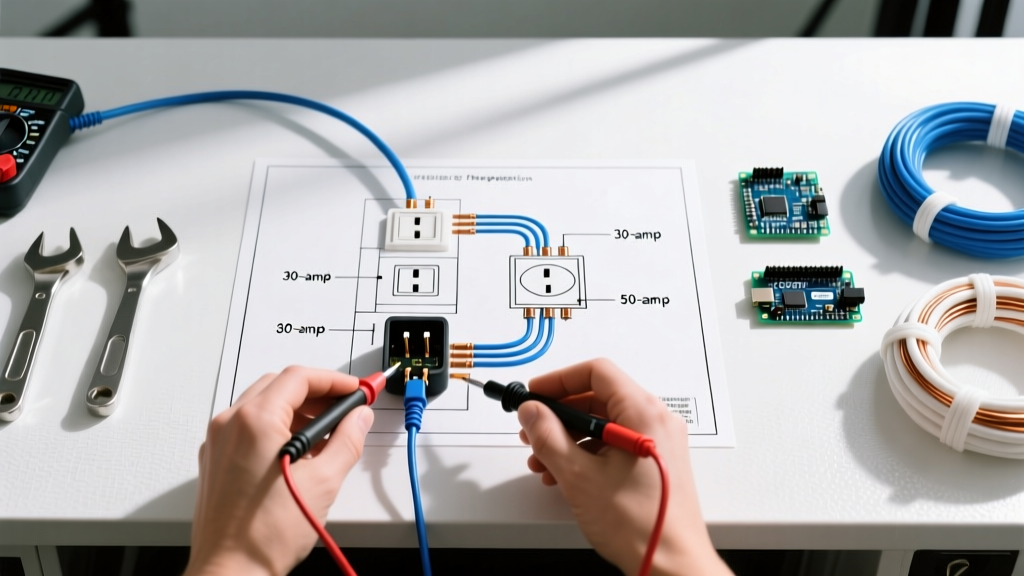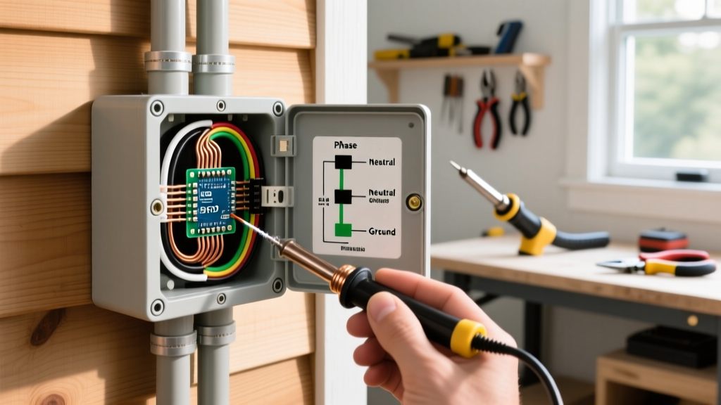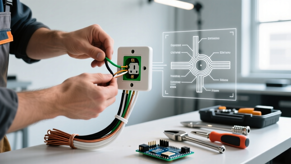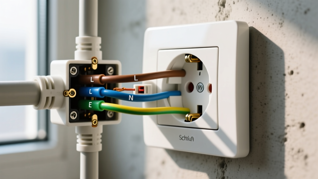

The Anatomy of a Duplex Receptacle: A Diagnostic Map
Most homeowners view a standard wall receptacle as a single, indivisible component. However, journeyman electricians understand that a 15-amp or 20-amp duplex outlet is a complex assembly of distinct electric outlet parts. When an outlet malfunctions, exhibits arcing, or fails to deliver power, pinpointing the exact failing component is the hallmark of expert troubleshooting. While replacing the entire unit is often the most practical fix, diagnosing the root cause prevents recurring failures, saves money on large-scale rewiring, and ensures compliance with the latest 2026 NEC (National Electrical Code) standards.
Before grabbing a screwdriver, you must understand the internal architecture of the device. Below is a diagnostic map of the primary electric outlet parts and their most common failure modes.
| Component | Material | Primary Function | Common Failure Mode |
|---|---|---|---|
| Faceplate (Cover) | Thermoplastic / Nylon | Protects internal wiring from physical contact | Cracking from overtightening or UV degradation |
| Yoke (Mounting Strap) | Galvanized Steel / Brass | Secures the receptacle to the electrical box | Bending, rust, or plaster ear breakage causing sag |
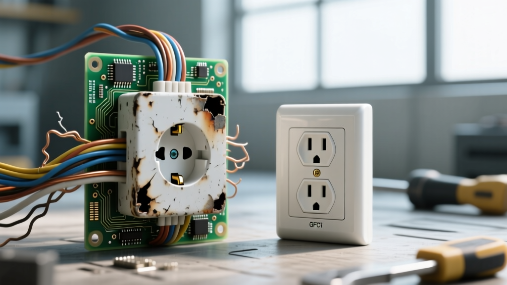
| Receptacle Body | Urea-formaldehyde / PBT | Houses and insulates internal contacts | Thermal melting due to high-resistance arcing |
| Wiping Contacts | Beryllium Copper / Brass | Grips the plug blades to conduct current | Loss of spring tension, leading to loose plugs |
| Terminal Screws | Brass (Hot) / Silver (Neutral) | Secures branch circuit wires to the device | Stripped threads, thermal loosening, or corrosion |
| Break-off Tabs (Fins) | Brass / Silver | Allows top/bottom split-wiring configurations | Accidental snapping or failure to snap when required |
Symptom-Based Troubleshooting Matrix
Effective diagnosis starts with the symptom, not the tool. Use this matrix to isolate which electric outlet parts are failing based on real-world behavior.
- Symptom: Plug falls out or feels loose. Culprit: Worn internal wiping contacts. Action: Replace the entire receptacle core; contacts cannot be serviced individually.
- Symptom: Buzzing or hissing sound when under load. Culprit: Loose terminal screw or failing push-in backstab connection causing micro-arcing. Action: Terminate the connection immediately, inspect wire insulation for scorching, and re-terminate using side-wire screws.
- Symptom: Faceplate is warm to the touch. Culprit: High resistance at the terminal, overloaded circuit, or poor internal contact tension. Action: Measure voltage drop and check for melted thermoplastic housing.
- Symptom: Outlet is completely dead, but breaker is ON. Culprit: Tripped upstream GFCI, broken backstab connection, or snapped internal bus bar. Action: Test for line voltage at the terminals; if present, the internal bus bar is fractured.
Deep Dive: Diagnosing Specific Part Failures
1. The Push-In Wire Connector (PIWC) Controversy
Also known as 'backstabbed' connections, PIWCs use a spring steel wedge to grip 14 AWG solid wire. While technically permitted by the NEC for specific wire gauges, these electric outlet parts are notorious for thermal failure. As current flows, the terminal heats up and expands; when the load is removed, it cools and contracts. Over years of thermal cycling, the spring steel loses its grip, increasing resistance and generating dangerous heat.
Expert Insight: According to the National Fire Protection Association (NFPA), loose or degraded electrical connections are a leading cause of residential electrical fires. If you open a dead outlet and find backstabbed wires, do not simply push them in deeper. Remove them, strip back to clean copper, and use the side-binding terminal screws or a UL-listed pigtail wire nut.
2. Wiping Contacts and the 'Dollar Bill' Test
The internal wiping contacts are the unsung heroes of the receptacle. They must maintain immense mechanical tension to grip plug blades securely. When these parts wear out, the resulting air gap causes arcing. To diagnose this without a thermal camera, electricians use the 'Dollar Bill Test': insert a dollar bill into the receptacle slots and pull. If there is no noticeable resistance, the wiping contacts have lost their spring tension and the receptacle is a fire hazard.
3. Break-off Tabs and Split-Receptacle Errors
The brass and silver fins connecting the top and bottom halves of an outlet are designed to be snapped off with needle-nose pliers. This allows for 'split-wiring'—where the top half is controlled by a wall switch and the bottom half remains always-on. A common diagnostic scenario: a homeowner replaces an outlet, forgets to snap the brass tab, and wires the switched hot to the top and constant hot to the bottom. The moment the wall switch is flipped, it creates a dead phase-to-phase short, instantly tripping the 15A or 20A breaker. If a newly installed outlet trips the breaker immediately, check the break-off tabs first.
Advanced Diagnostic Tools for Electric Outlet Parts
Visual inspection only goes so far. To accurately diagnose failing electric outlet parts, you need precision instruments. Here is the 2026 standard toolkit for outlet diagnostics:
- Non-Contact Voltage Tester (NCVT): The Klein Tools NCVT-2 (~$28) detects AC voltage from 12V to 1000V. Use this to verify the circuit is dead before removing the faceplate.
- Receptacle Tester: The Gardner Bender GRT-3200 (~$14) quickly identifies miswired conditions like open neutrals, reversed polarity, or missing grounds.
- True-RMS Multimeter: Essential for voltage drop testing. A standard Fluke 117 (~$220) allows you to measure millivolt drops across the receptacle under load.
- Thermal Imaging Camera: Tools like the FLIR C5 (~$450) instantly reveal hot spots on the yoke or faceplate, indicating high-resistance connections hidden behind the wall.
Performing a Voltage Drop Test
To diagnose internal bus bar degradation, perform a voltage drop test under load. The Occupational Safety and Health Administration (OSHA) emphasizes that excessive voltage drop indicates dangerous resistance in the circuit path.
- Plug a high-draw appliance (like a 1500W space heater drawing ~12.5A) into the outlet.
- Set your multimeter to AC Millivolts (mV).
- Place one probe on the hot wire where it enters the electrical box, and the other probe on the hot slot of the receptacle face.
- A healthy receptacle will show a drop of less than 50mV. If you read 200mV or higher, the internal brass bus bar or terminal screws are failing and the unit must be replaced.
Replacement Matrix: Choosing the Right Grade
When your diagnosis confirms that the electric outlet parts are beyond repair, selecting the correct replacement grade is critical. Builder-grade outlets use thinner thermoplastics and lower-grade steel yokes that fail prematurely. Below is a comparison of receptacle grades available in 2026.
| Grade | Example Model | Avg. Cost (2026) | Yoke Material | Best Application |
|---|---|---|---|---|
| Builder / Residential | Leviton 5262-E | $0.90 - $1.25 | Plated Steel | Low-use areas, guest rooms, closets |
| Commercial Spec | Leviton 5362-E | $3.50 - $4.80 | Galvanized Steel | Kitchens, living rooms, home offices |
| Hospital / Isolated Ground | Hubbell IG5362 | $11.00 - $14.50 | Heavy Brass/Steel | Medical equipment, sensitive AV gear |
For 90% of residential troubleshooting replacements, upgrading to a Commercial Spec grade outlet is the most cost-effective solution. The thicker beryllium copper wiping contacts and robust steel yokes drastically reduce the likelihood of future mechanical failures.
Safety and Code Compliance
Diagnosing and replacing electric outlet parts is not just about restoring power; it is about maintaining the safety envelope of your home's electrical system. The U.S. Consumer Product Safety Commission (CPSC) strongly advises against using damaged or modified receptacles. Always ensure that when replacing an outlet, the ground screw is tightly secured to the bare copper ground wire, and the cable clamp inside the electrical box is tightened to prevent strain on the terminal screws. If you encounter aluminum wiring (common in homes built between 1965 and 1973), standard copper-rated outlets are a severe fire hazard; you must use CO/ALR rated devices or pigtail with approved copper-to-aluminum connectors.