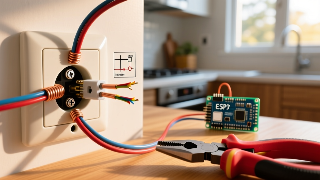

The Anatomy of a Standard 15A/20A Receptacle
Understanding how to connect wires to electrical outlet terminals is the foundation of residential and commercial electrical safety. A poorly terminated 15A or 20A receptacle is not just a code violation; it is a primary ignition source for electrical fires. According to the National Fire Protection Association (NFPA), electrical distribution equipment remains a leading cause of structural fires. This wiring diagram reference provides exact terminal mappings, NEC-mandated torque specifications, and professional techniques to ensure your installations are bulletproof.
Before stripping any wire, you must understand the terminal layout of a standard NEMA 5-15R or 5-20R duplex receptacle. Whether you are installing a standard residential Leviton 5320-WCP (approx. $1.50) or a commercial-grade Hubbell H5262A (approx. $4.25), the terminal geometry remains consistent:
- Brass Terminal Screws: The ungrounded (hot) conductor connection point.
- Silver Terminal Screws: The grounded (neutral) conductor connection point.
- Green Terminal Screw: The equipment grounding conductor (EGC) connection point.
Wire-to-Terminal Mapping Matrix
The National Electrical Code (NEC) strictly dictates which wire insulation colors map to specific terminal screws. Reversing the hot and neutral (creating reversed polarity) is a severe shock hazard that will trip a standard plug-in tester immediately.
| Wire Insulation Color | Terminal Screw Color | NEC Article Reference | Conductor Function |
|---|---|---|---|
| Black, Red, or Blue | Brass | NEC 200.2 / 406 | Ungrounded (Hot / Line) |
| White or Gray | Silver | NEC 200.2 | Grounded (Neutral) |
| Bare Copper or Green | Green | NEC 250.118 | Equipment Grounding |
Step-by-Step Termination Procedure
Professional electricians do not rely on guesswork. Follow this exact sequence to achieve a low-resistance, high-integrity mechanical connection.
1. Precision Wire Stripping
Use a dedicated wire stripper, such as the Klein Tools 11055, set precisely to the gauge of your conductor (typically 14 AWG for 15A circuits or 12 AWG for 20A circuits). Strip exactly 3/4 inch (19mm) of insulation. If you strip too little, the insulation will bind under the screw head, creating a high-resistance fault. If you strip too much, you will leave bare copper exposed outside the terminal yoke, creating a short-circuit hazard.
2. Forming the J-Hook
Using the needle-nose pliers built into your wire strippers, bend the exposed copper into a tight 'J' hook. The radius of the hook should perfectly match the radius of the terminal screw shaft. This ensures maximum surface area contact between the copper and the brass/silver terminal plate.
3. Clockwise Routing
Loop the J-hook around the terminal screw in a clockwise direction. This is a critical mechanical detail: as you tighten the screw (which turns clockwise), the screw head will pull the wire loop tighter around the shaft. If routed counter-clockwise, the tightening action will push the wire out from under the screw head.
4. Torque Verification
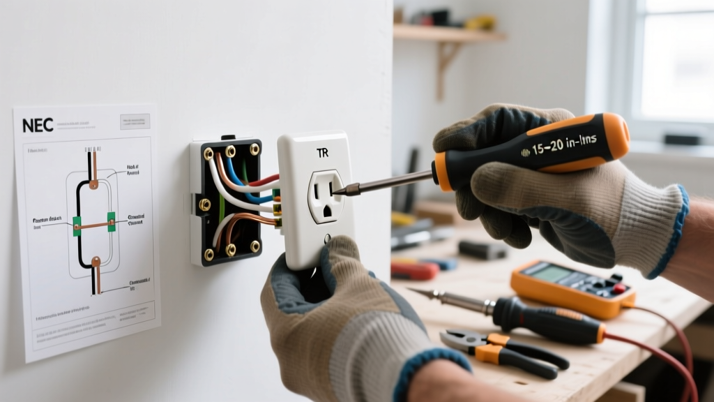
Under NEC 110.14(D), all electrical connections must be tightened to the manufacturer's specified torque. For almost all modern 15A and 20A receptacles, the required torque is 14 in-lbs (inch-pounds). Use a calibrated torque screwdriver, such as the Wiha 64500, to achieve this exact spec. Hand-tightening often leads to under-torquing, which causes thermal expansion and contraction cycles to loosen the connection over time, eventually leading to arc faults.
The 'Backstab' Push-In Connector Failure Mode
Expert Warning: Never use the push-in (backstab) terminals found on the rear of builder-grade receptacles. While technically UL-listed, they rely on a small internal spring-steel wiper to maintain contact with the wire.
According to the Electrical Safety Foundation International (ESFI), loose connections are a primary driver of residential electrical fires. Push-in terminals are highly susceptible to thermal cycling. As the receptacle is loaded (e.g., running a 12A space heater), the internal brass contacts heat up and expand. When the load is removed, they cool and contract. Over hundreds of cycles, the internal spring fatigues, the contact pressure drops, and electrical arcing begins inside the plastic housing. Always use the side-binding screw terminals for a permanent mechanical connection.
Pigtailing vs. Feed-Through (Daisy Chaining)
When wiring multiple outlets on a single branch circuit, you must decide between feed-through wiring and pigtailing.
- Feed-Through: The incoming and outgoing wires are both terminated under the same terminal yoke (using the top and bottom screws on the same side). While acceptable for the hot and ground conductors, this is dangerous for the neutral.
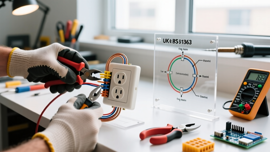
- Pigtailing: Incoming and outgoing wires are joined with a short jumper wire (pigtail) using a wire nut or Wago 221 lever connector. The single pigtail is then terminated to the receptacle screw.
NEC 300.13(B) Requirement: The continuity of the grounded (neutral) conductor in a multiwire branch circuit or standard daisy-chained circuit must not depend on the receptacle itself. If you feed-through the neutral and the receptacle is removed for replacement, the downstream neutral is severed, which can cause severe overvoltage conditions on downstream devices. Always pigtail the neutral conductor.
Grounding and Box Bonding (NEC 250.148)
The equipment grounding conductor (EGC) must do two things: it must terminate to the green screw on the receptacle, and it must bond to the metal electrical box (if applicable). If you are working with a metal junction box or a metal mud ring, use a green grounding pigtail and a grounding clip (or a #10-32 grounding screw) to bond the bare copper to the box. Failure to bond the box leaves the metal enclosure energized in the event of a ground fault, bypassing the breaker's protection entirely.
Troubleshooting Common Termination Faults
| Symptom | Root Cause | Corrective Action |
|---|---|---|
| Receptacle tester shows 'Open Neutral' | Silver terminal screw under-torqued, or neutral wire severed during stripping. | Re-strip wire to 3/4 inch, re-terminate to silver screw, torque to 14 in-lbs. |
| Receptacle tester shows 'Hot/Neutral Reverse' | Black (hot) wire landed on silver screw; White (neutral) landed on brass screw. | Swap conductors to match NEC color-to-terminal mapping matrix. |
| Burn marks on plastic yoke after 6 months | Push-in backstab terminal used, or side screw not torqued, causing high-resistance arcing. | Replace receptacle entirely. Terminate using side screws and a torque screwdriver. |
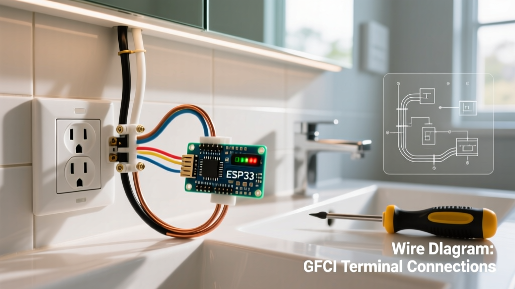
| GFCI trips immediately upon reset | Line and Load terminals reversed, or neutral pigtail touching ground. | Verify incoming power is on 'LINE' terminals only. Ensure bare copper is not shorting to silver screws. |
Final Inspection and Energization
Before installing the receptacle into the junction box, perform a visual and physical inspection. Tug gently on each wire to ensure it is locked under the screw head. Verify that no bare copper is visible outside the terminal yoke. Fold the wires neatly into the back of the box—pushing the receptacle in with bent or crushed wires can cause insulation damage and short circuits against the metal box edges. Once secured with the #6-32 mounting screws, use a non-contact voltage tester and a standard 3-light receptacle tester to verify correct wiring before plugging in any loads. For comprehensive workplace safety standards regarding energized testing, always consult OSHA Electrical Safety Standards.