
The Dual-Load Dilemma: Why Standard 3-Way Diagrams Fail
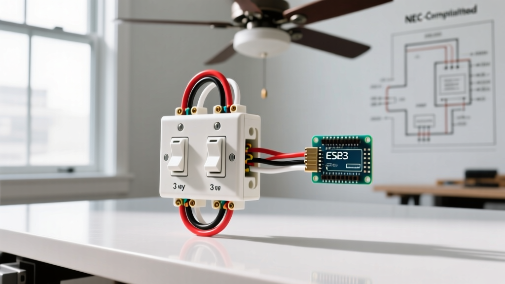
When homeowners search for a 3 way switch wiring diagram for ceiling fan installations, they often encounter a frustrating roadblock: standard 3-way diagrams only account for a single load (like a simple hallway light). However, a modern ceiling fan with an integrated light kit represents a dual-load scenario. If you want to control the fan motor and the light kit independently from two different wall locations, a standard 14/3 NM-B cable is mathematically and physically insufficient. You are attempting to route two separate switched legs, two sets of travelers, and a neutral wire through a single conduit or cable pathway.
In this comprehensive 2026 installation guide, we will break down the exact wiring topology required to achieve independent dual-load 3-way control, detail the National Electrical Code (NEC) box fill requirements that most DIYers ignore, and provide a modern smart-switch alternative that eliminates the need for pulling new 4-conductor cables.
⚠️ NEC Safety & Box Fill Warning: According to NFPA 70 (NEC) Article 314.16, adding multiple 3-way switches and 14/4 cables to a standard single-gang box will almost certainly violate box fill capacities. Always upgrade to deep 22-cubic-inch or larger boxes before beginning this specific dual-load wiring topology.Essential Tools and Materials Matrix
Before pulling any wire, ensure you have the correct materials. Using 15A rated components on a 20A circuit is a severe fire hazard. The matrix below outlines the exact specifications required for a standard 15-Amp residential lighting circuit.
| Item | Specification / Model | Estimated Cost (2026) | NEC / Technical Note |
|---|---|---|---|
| Wiring Cable | Southwire 14/4 NM-B (Solid) | $1.15 / linear ft | Required for independent dual-load 3-way control. |
| Wall Switches | Leviton Decora 15A 3-Way (R62-05603-2WS) | $4.85 each (x4) | Requires 4 total switches (2 for fan, 2 for light). |
| Wall Boxes | Carlon 2-Gang Deep (B620-UPC) | $3.20 each | Minimum 34 cu. in. capacity for dual 3-way setups. |
| Torque Screwdriver | Klein Tools 70002 (Torque range 10-40 in-lbs) | $85.00 | NEC 110.14(D) mandates calibrated torque for terminals. |
| Wire Connectors | Ideal SureWire 2-Port / 3-Port Lever Nuts | $0.45 each | Allows for easy troubleshooting without twisting wires. |
Decoding the 3 Way Switch Wiring Diagram for Ceiling Fan Units
To achieve independent control, you must essentially run two parallel 3-way circuits sharing a single neutral and ground pathway. This is where the 14/4 NM-B cable becomes mandatory. Here is the conductor breakdown for the cable running between Switch Box A (Line side) and Switch Box B (Load side):
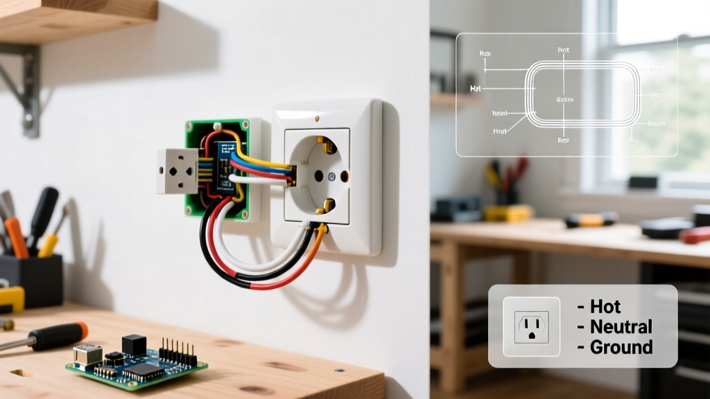
- White Wire: Shared Neutral (spliced through both boxes, never switched).
- Bare Copper: Shared Equipment Grounding Conductor.
- Black Wire: Traveler 1 for the Fan Motor circuit.
- Red Wire: Traveler 2 for the Fan Motor circuit.
- Blue Wire: Switched Leg / Traveler pathway for the Light Kit circuit.
Note: Because a standard 14/4 cable only provides three colored conductors (Black, Red, Blue) alongside the white neutral, routing two complete sets of travelers (which require four colored wires) through a single 14/4 cable is impossible. Therefore, the true hardwired diagram requires pulling two separate 14/3 NM-B cables between the switch boxes, OR utilizing the 2026 smart-switch topology detailed later in this guide.
Step-by-Step Hardwired Installation (Dual 14/3 Method)
For the purist insisting on a fully hardwired, traditional mechanical switch setup, you must pull two distinct 14/3 cables between the two wall boxes to accommodate the four required traveler wires.
Step 1: Box Fill Calculation and Preparation
Calculate the cubic inch requirements. For 14 AWG wire, the NEC assigns a volume allowance of 2.0 cubic inches per conductor. Each 3-way switch counts as two conductors (4.0 cu in). With two 14/3 cables entering the box, plus pigtails and grounds, a standard 18 cu in box will overflow, causing drywall bulging and heat entrapment. Install a minimum 34 cu in dual-gang box at both locations.
Step 2: Wiring Switch Box A (The Line Side)
At the first box, you will have your incoming 14/2 power feed (Line, Neutral, Ground) and the two outgoing 14/3 cables heading to Box B.
- Neutrals: Pigtail all white neutral wires together using a lever nut. Do not attach them to the switches.
- Grounds: Bond all bare copper wires together and pigtail to the green ground screws on both 3-way switches.
- Line In: Connect the incoming hot (black) from the breaker to a wire nut, splitting it into two separate pigtails. Attach one pigtail to the 'Common' (black) screw on the Fan 3-way switch, and the other to the 'Common' screw on the Light 3-way switch.
- Travelers Out: Connect the Black and Red wires of the first 14/3 cable to the brass traveler screws on the Fan switch. Connect the Black and Red wires of the second 14/3 cable to the brass traveler screws on the Light switch.
Step 3: Wiring Switch Box B (The Load Side)
At the second box, you will receive the two 14/3 cables and send a single 14/4 (or 14/2 + 14/3) cable up to the ceiling fan canopy.
- Wire the incoming travelers to the brass screws on the corresponding new 3-way switches, matching the colors from Box A.
- The 'Common' (black) screw on the Fan switch gets the black wire heading up to the fan canopy.
- The 'Common' (black) screw on the Light switch gets the red wire heading up to the fan canopy.
Step 4: Canopy Integration and Torque Verification
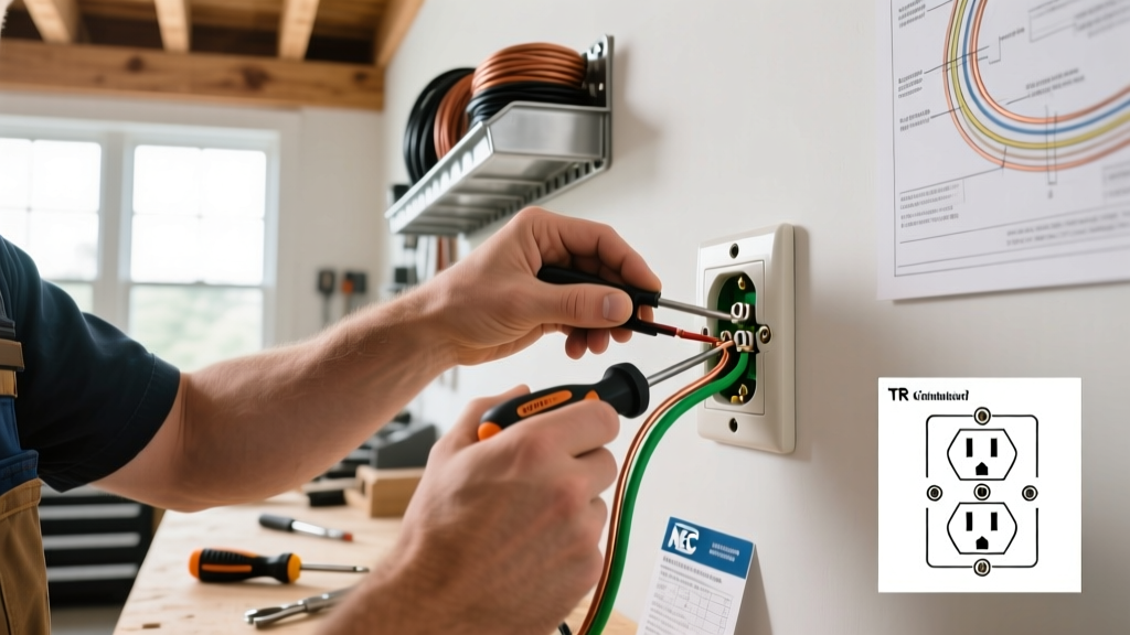
At the ceiling fan canopy, connect the incoming black wire to the fan motor's 'L' or 'Hot' lead, and the incoming red wire to the light kit's blue wire. Connect all whites to the canopy white, and all grounds to the mounting bracket ground screw. Using your calibrated torque screwdriver set to 14 in-lbs (standard for 14 AWG on Leviton Decora terminal screws), tighten all terminal screws. This satisfies NEC 110.14(D) and prevents arc-faulting from loose mechanical connections over time.
The 2026 Pro-Tip: The Smart Switch Bypass (Lutron Caseta)
Pulling two 14/3 cables through finished walls is a drywall-destroying nightmare. In 2026, master electricians overwhelmingly recommend bypassing the mechanical 3-way traveler dilemma entirely by using smart fan controllers and wireless remotes. This reduces your wiring requirements back to a single, standard 14/3 cable.
Expert Insight: By installing a Lutron Caseta PD-FSQX fan controller and a PD-5WS-DV light switch at the primary location, you can mount wireless Pico remotes (PJ2-3BRL) at the secondary 3-way location. The Pico remotes communicate via Lutron's Clear Connect RF protocol (which operates on a different frequency than Wi-Fi, ensuring zero latency or interference). This achieves independent 3-way control while only requiring a single 14/3 cable between the primary switch and the fan canopy.
This method not only saves hours of fishing wire through wall cavities but also integrates seamlessly with modern home automation ecosystems, allowing for scheduled fan operation to reduce HVAC loads—a key focus of the U.S. Department of Energy's ceiling fan efficiency guidelines.
Troubleshooting Common Wiring Faults
If your mechanical 3-way setup is behaving erratically, consult this diagnostic matrix before tearing open the drywall:
| Symptom | Probable Cause | Diagnostic Solution |
|---|---|---|
| Fan only works when Light switch is ON. | Shared neutral is broken or miswired as a switched leg. | Use a non-contact voltage tester at the canopy to verify the white wire is continuously hot-neutral, not a return leg. |
| Switches must be in specific toggled positions to work. | Traveler and Common wires are swapped on one of the 3-way switches. | Identify the black 'Common' screw. Ensure the Line (Box A) or Load (Box B) is on this screw, NOT a brass traveler screw. |
| Breaker trips immediately upon flipping switch. | Ground wire is pinched against a hot traveler inside the wall box. | Inspect box fill. If wires are jammed, the insulation on the traveler may be compromised. Re-strip and use lever nuts to reduce bulk. |
Final Safety Verification
Always adhere to the guidelines set forth by the Electrical Safety Foundation International (ESFI) when working with dual-load circuits. Before restoring power at the main panel, perform a continuity test with a multimeter across the hot and ground wires to ensure no dead shorts exist in the canopy or wall boxes. A successful 3-way ceiling fan installation relies not just on following a diagram, but on respecting the physical volume constraints of your electrical boxes and the precise torque requirements of modern NEC standards.