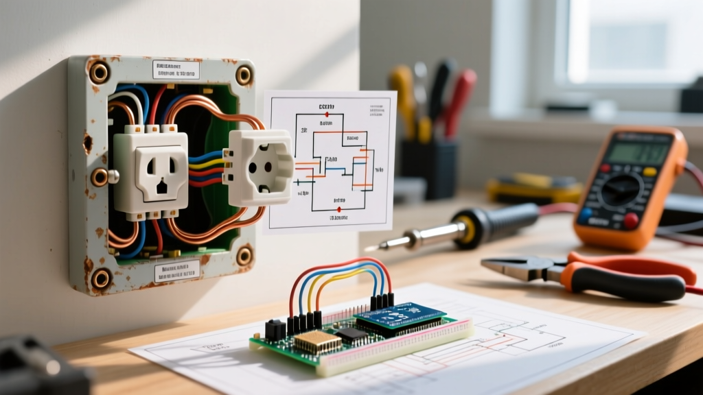
A standard 2 outlet wiring diagram connects two duplex receptacles on a single branch circuit. The most common and code-compliant default for general-purpose rooms is a Standard Parallel (Daisy-Chain) configuration using 12/2 NM-B cable on a 20A dual-function (AFCI/GFCI) breaker. This guide walks you through the exact terminal anatomy, decodes the schematic symbols, traces the current path from source to load, and provides the exact meter readings you need to verify a safe installation.
The Decision Path: Standard Parallel vs. Split-Wired
Before stripping any wire, you must determine the functional intent of the two outlets. Misidentifying the circuit topology is the leading cause of tripped breakers and melted tabs in DIY wiring. Use this decision tree to lock in your configuration.
| Condition / Requirement | Standard Parallel | Split-Wired (Switched) |
|---|---|---|
| Are both top and bottom halves of both outlets always hot? | YES | NO |
| Is one half of the outlet controlled by a wall switch? | NO | YES |
| Cable Required | 12/2 NM-B (Black, White, Bare) | 12/3 NM-B (Black, Red, White, Bare) |
| Receptacle Prep | Leave brass fin intact | Break off brass (hot) fin |
Decoding the 2 Outlet Wiring Diagram Symbols
Electrical schematics use standardized NEC/IEEE symbols to represent physical components. When reading a 2 outlet wiring diagram, you will encounter these specific glyphs:
- The Receptacle Symbol: A semicircle with two parallel lines extending from the flat edge. This represents a standard duplex NEMA 5-15R or 5-20R outlet. If the semicircle has a slash through it, it indicates a switched half (split-wired).
- The Ground Symbol: Three horizontal lines of decreasing width stacked vertically, or a circle with a downward-pointing arrow. In wiring diagrams, this represents the Equipment Grounding Conductor (EGC) path back to the panel's ground bar.
- The Splice Node: A solid black dot where two lines intersect. This indicates a physical wire splice (usually a wire nut or Wago connector) inside the junction box. If lines cross without a dot, they do not connect.
- The Breaker Symbol: A rectangle with a toggle switch inside, labeled with its ampacity (e.g., '20A'). This represents the overcurrent protective device at the source.
Terminal Mapping and Physical Device Anatomy
A standard 20A duplex receptacle (like the Leviton 5362 or Eaton TRCR20W) features six terminal screws and one grounding clip. Understanding which terminal accepts which wire is critical for maintaining correct polarity.
| Terminal Color | Function | Wire Color (12/2 NM-B) | Torque Spec (Typical 12 AWG) |
|---|---|---|---|
| Brass (Gold) | Hot / Ungrounded Conductor | Black | 12 in-lbs |
| Silver | Neutral / Grounded Conductor | White | 12 in-lbs |
| Green | Equipment Ground (EGC) | Bare Copper | 12 in-lbs |
Note: Always verify the exact torque specification stamped on the back of your specific receptacle yoke. Under-torqued terminals cause high-resistance faults and arcing; over-torquing strips the screw threads or damages the wire strands.
Node-by-Node Trace: Source to Load Path
Let's trace the current path for a Standard Parallel 2 outlet wiring diagram, starting from the panel and ending at the second receptacle. This trace explicitly defines polarity and the ground path.
1. The Source (Panel): The 20A breaker clamps onto the hot bus bar. A 12/2 NM-B cable exits the panel. The black wire (Hot) originates here. The white wire (Neutral) terminates on the panel's neutral bar. The bare wire (Ground) terminates on the panel's ground bar.
2. Entering Outlet 1 (Line Side): The 12/2 cable enters the first junction box.
• Hot Path: The black wire is stripped to 3/4 inch and loops clockwise around the top Brass screw (Line side).
• Neutral Path: The white wire is pigtailed. A 6-inch white pigtail connects the incoming white wire to a second white wire using a wire nut. The pigtail loops around the top Silver screw.
• Ground Path: The bare copper wire is pigtailed to a 6-inch bare pigtail, which terminates on the Green ground screw.
3. Bridging to Outlet 2 (Load Side to Line Side): A second 12/2 NM-B cable runs from Box 1 to Box 2.
• Hot Path: A black wire connects to the bottom Brass screw (Load side) of Outlet 1, runs through the wall, and connects to the top Brass screw (Line side) of Outlet 2.
• Neutral Path: The downstream white wire in Box 1 joins the incoming white wire and the Outlet 1 pigtail under the same wire nut. The downstream white wire runs to Box 2 and connects to the top Silver screw of Outlet 2.
• Ground Path: The downstream bare wire in Box 1 joins the ground splice, runs to Box 2, and terminates on the Green screw of Outlet 2.
Step-by-Step Installation and Torque Specs
- De-energize and Verify: Turn off the 20A breaker. Test the existing wires in the box with an NCVT and a multimeter to confirm 0V.
- Prep the Conductors: Strip exactly 3/4 inch of insulation from the 12 AWG THHN/NM-B conductors using wire strippers. Do not nick the copper; nicks create weak points that snap under torque.
- Form the Ground Splice: Twist the incoming bare wire, the outgoing bare wire, and a 6-inch bare pigtail together. Secure with a tan or red wire nut (rated for three 12 AWG wires). Attach the pigtail to the green ground screw and torque to 12 in-lbs.
- Form the Neutral Splice: Twist the incoming white, outgoing white, and a 6-inch white pigtail together. Cap with a yellow wire nut. Attach the pigtail to the silver screw. Ensure no bare copper is exposed outside the terminal clamp.
- Terminate the Hot Wires: Loop the incoming black wire onto the top brass screw. Loop the outgoing black wire onto the bottom brass screw. Torque both to 12 in-lbs using a calibrated torque screwdriver.
- Fold and Secure: Carefully fold the ground wires into the back of the box first, followed by the neutral bundle, and finally the hot wires. Push the receptacle in, ensuring it sits flush, and secure with the provided 6-32 mounting screws.
Meter Verification: Proving the Circuit is Correct
Never assume a wiring diagram was executed perfectly just because the breaker didn't trip immediately upon energizing. You must verify the electrical characteristics with a digital multimeter (DMM) set to AC Voltage (V~).
With the 20A breaker turned ON, insert your multimeter probes into the slots of Outlet 1 and Outlet 2, taking the following measurements:
- Hot to Neutral (Short slot to Long slot): Must read between 114V and 126V (120V nominal). If you read 0V, you have an open hot or open neutral. If you read 240V, you have mistakenly wired it to a 240V breaker or an MWBC without a handle tie.
- Hot to Ground (Short slot to U-shaped ground hole): Must read 114V to 126V. This confirms the equipment grounding conductor is continuous back to the panel and bonded to the neutral at the main service disconnect.
- Neutral to Ground (Long slot to U-shaped ground hole): Must read less than 2V (ideally 0.0V to 0.5V). If you read 120V here, your hot and neutral are reversed (reverse polarity). If you read 2V to 5V, you have excessive voltage drop or a loose neutral connection upstream.
Finally, plug in a commercial receptacle tester (like the Gardner Bender GFI-3501). The lights should indicate 'Correct' (usually two yellow/amber lights). If the tester indicates 'Open Ground' or 'Hot/Neu Reverse', de-energize the panel and re-check your terminal mapping against the spec sheet above.
For further reading on branch circuit requirements and grounding mandates, refer to the National Fire Protection Association (NFPA) NEC resources and the OSHA Electrical Safety guidelines for safe workspace practices.