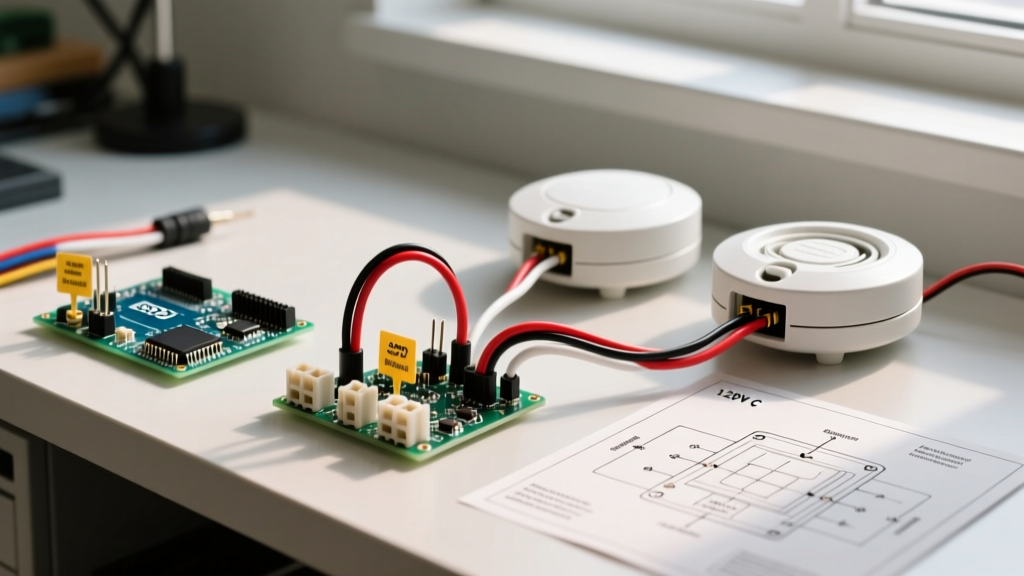

Mastering the Wiring for Smoke Alarms Diagram: A Home Project Guide
Upgrading or installing hardwired smoke detectors is one of the most critical safety projects you can undertake in your home. While battery-operated units offer basic protection, modern building codes and safety standards heavily favor interconnected, hardwired systems. When one alarm detects smoke, they all sound, giving your family maximum warning time. However, transitioning from a simple single-wire fixture to a multi-node network requires a solid understanding of a wiring for smoke alarms diagram. This guide breaks down the electrical topology, National Electrical Code (NEC) requirements, and step-by-step installation procedures for 120V interconnected smoke alarms in 2026.
Safety Warning: Always shut off the main breaker to the circuit you are working on and verify it is dead using a non-contact voltage tester (like the Klein Tools NCVT-3) before touching any wires. Working on live 120V circuits can be fatal.
Decoding the Standard Wiring for Smoke Alarms Diagram
When you look at a standard wiring for smoke alarms diagram, you will notice it relies on a 3-wire cable setup to create a 'daisy-chain' loop. Unlike standard lighting circuits that use 2-wire (14/2 or 12/2) cables, interconnected smoke alarms require a third wire to carry the interconnect signal.
The 3-Wire Conductor Breakdown
In a typical residential installation using 14/3 NM-B (Romex) cable, the diagram will map the conductors as follows:
- Black Wire (Line/Hot): Carries the 120V AC power from the breaker panel to the first alarm, and continues to feed power to subsequent alarms in the chain.
- White Wire (Neutral): Completes the 120V AC circuit, providing the return path to the panel.
- Red Wire (Interconnect/Traveler): This is the communication wire. It carries a 9V DC signal between units. When one alarm triggers, it sends a voltage spike down the red wire, telling all other alarms on the same red wire network to sound their horns.
Daisy-Chain vs. Star Topology
A proper wiring for smoke alarms diagram will always depict a daisy-chain (series) topology. Power enters the first alarm, then a 3-wire cable runs from the first alarm to the second, from the second to the third, and so on. Never use a 'star' or 'home-run' topology where individual 3-wire cables run from a central junction box to each alarm. This can cause signal reflection issues and voltage drops on the DC interconnect line, leading to delayed triggering or failure to interconnect.
NEC and NFPA Code Requirements for Interconnects
Before pulling any wire, you must understand the legal and safety frameworks governing these installations. According to the National Fire Protection Association (NFPA) and the NEC, specific rules apply to smoke alarm circuits.
NFPA 72 Interconnection Mandate
The NFPA 72 National Fire Alarm and Signaling Code requires that where more than one smoke alarm is required within an individual dwelling unit, they must be interconnected so that the activation of one alarm initiates the audible alarm signal of all smoke alarms within the unit. This applies to new construction and major remodels where drywall is removed down to the studs.
AFCI and Branch Circuit Rules
Under NEC Article 210.12, most bedroom and living area circuits require Arc-Fault Circuit Interrupter (AFCI) protection. However, putting smoke alarms on an AFCI-protected circuit can lead to nuisance tripping. If the AFCI breaker trips, your hardwired alarms lose primary power and fall back to their 9V backup batteries, which will eventually drain and cause 'low battery' chirping. Pro Tip: Many electricians dedicate a specific 15A non-AFCI circuit solely for smoke alarms and bathroom exhaust fans (where permitted by local amendments) to ensure the life-safety circuit is never interrupted by a nuisance arc-fault trip from a vacuum cleaner in a bedroom.
Step-by-Step Installation: Following the Diagram
Here is how to physically execute the wiring for smoke alarms diagram using modern materials. For this project, we assume you are installing standard 120V hardwired units like the Kidde i12060 (approx. $24 per unit) or the First Alert SA720CN (approx. $18 per unit).
- Rough-In the Cable: Run 14/3 NM-B cable (costing roughly $0.70 per foot in 2026) from the power source to the first electrical box, and then from box to box. Leave at least 8 inches of slack protruding from each ceiling box.
- Strip the Sheathing and Insulation: Strip back the outer PVC sheathing to expose the wires. Using a precision wire stripper, remove exactly 3/4 inch of insulation from the black, white, and red wires. Stripping too little causes loose connections; stripping too much exposes bare copper outside the wire nut, creating a short-circuit hazard.
- Create Pigtails: Do not wrap the wires directly around the alarm's terminal screws if the unit provides a quick-connect harness. Instead, use the provided wiring harness. Connect the harness's black wire to the ceiling's black wires using an Ideal 339 (Tan) wire nut. Connect the whites together, and the reds together.
- Secure the Interconnect: Ensure the red interconnect wires are securely twisted together before applying the wire nut. A loose red wire is the #1 cause of 'single-alarm-only' sounding during a fire event.
- Mount and Test: Attach the mounting bracket to the ceiling box using the provided #8-32 screws. Twist the alarm onto the bracket. Once all units are installed and the breaker is turned on, test the system using canned smoke tester (like SD-6000, approx. $12) rather than just the test button, to verify the optical/ionization sensors are actually detecting particulates.
Conductor Color Mapping Matrix
While 14/3 NM-B is standard, older homes or commercial harnesses might use different color codes. Use this matrix to cross-reference your wiring for smoke alarms diagram against the physical wires in your ceiling.
| Function | Standard 14/3 NM-B | Older / Commercial Harness | Terminal Label on Alarm |
|---|---|---|---|
| 120V Line (Hot) | Black | Black or Blue | LINE / HOT / BK |
| 120V Neutral | White | White or Grey | NEUTRAL / WHT |
| DC Interconnect | Red | Yellow, Orange, or Red | INTERCONNECT / RED |
Hardwired vs. Wireless Interconnect: A 2026 Comparison
If your home is already finished and running 14/3 wire through drywall is cost-prohibitive, you might consider wireless interconnects. Here is how they compare to the traditional hardwired diagram approach.
| Feature | Hardwired (14/3 NM-B) | Wireless RF Interconnect |
|---|---|---|
| Installation Cost | High (Drywall repair, wire, labor) | Low (Swap and play) |
| Reliability | Extremely High (Physical copper path) | Moderate (Subject to RF interference) |
| Max Units per Network | Up to 24 (per NFPA 72 limits) | Usually 12 to 18 units |
| Code Compliance (New Build) | Required by NEC / IRC | Not permitted for new construction |
Troubleshooting Common Diagram Misinterpretations
Even when you follow the wiring for smoke alarms diagram perfectly, edge cases can occur. Here is how to troubleshoot the most common issues faced by DIYers and professional electricians alike.
The 'Ghost Chirp' Voltage Drop
If your alarms randomly chirp once a month, but the batteries are brand new, you may be experiencing voltage drop on the interconnect line. If your daisy-chain run exceeds 500 feet of 14 AWG wire, the resistance can degrade the 9V DC signaling voltage. The alarms interpret this degraded signal as a fault or low battery. Fix: Upgrade the interconnect run to 12 AWG wire, or split the alarms onto two separate branch circuits with a relay module.
Mixing Brands on the Red Wire
A frequent mistake is mixing Kidde and First Alert alarms on the same red interconnect wire. While both use the red wire for signaling, their internal logic boards sometimes interpret the DC voltage spikes differently, leading to a scenario where a Kidde alarm triggers, but the First Alert units remain silent. According to the U.S. Consumer Product Safety Commission (CPSC), you should always use the same manufacturer and model family for all interconnected alarms to ensure compatible signaling protocols.
Integrating Smart Home Alarms
If you are upgrading to smart alarms like the Google Nest Protect, note that they do not use the traditional red wire interconnect. They rely on Wi-Fi and 802.15.4 Thread mesh networks. If you have a hardwired diagram with a red wire, you must cap the red wire off with a wire nut and tuck it safely into the box. If you want to integrate a Nest Protect with existing older hardwired dumb alarms, you must install a Kidde SM120X Real-Time Smoke Notification Adapter to bridge the physical red wire signal to a smart home hub via dry-contact relays.
Final Safety and Maintenance Checks
Once your wiring for smoke alarms diagram has been fully implemented and the system is live, maintenance is key. The U.S. Fire Administration (USFA) recommends testing interconnected alarms monthly using the test button, and replacing the entire hardwired unit every 10 years, as the internal radioactive isotopes (in ionization models) and photoelectric sensors degrade over time. Always write the installation date on the rim of the alarm with a Sharpie so future homeowners know exactly when the 10-year lifecycle expires.
By strictly adhering to the 3-wire topology, respecting NEC branch circuit rules, and using high-quality connectors, your hardwired smoke alarm network will provide decades of reliable, life-saving performance.