
The Critical Reality of 240V/50-Amp Appliance Circuits
When it comes to high-load residential appliances, wiring electric stove connections represents one of the most unforgiving tasks in home electrical work. A standard electric range draws between 40 and 50 amps at 240 volts, translating to roughly 12,000 watts of continuous thermal and electrical energy. A loose termination, an undersized conductor, or an improperly grounded chassis doesn't just trip a breaker—it creates a severe arc flash hazard and a direct pathway for structural fires.
According to the Consumer Product Safety Commission (CPSC), electrical distribution and lighting equipment are consistently among the top causes of residential fire deaths. To mitigate these risks, modern electrical codes have drastically updated the requirements for range circuits. This guide details the exact safety protocols, material specifications, and National Electrical Code (NEC) mandates you must follow when installing or upgrading a 50-amp stove circuit.
Anatomy of a Code-Compliant 50-Amp Stove Circuit
Before stripping a single wire, you must verify that your materials match the strict requirements for a 50-amp continuous/intermittent load. Undersizing any component in this chain violates NEC Article 210 and voids the appliance warranty.
| Component | Required Specification | Recommended Brand/Model (2026) |
|---|---|---|
| Circuit Breaker | 50-Amp, 2-Pole, 240V | Square D QO250 (with Visi-Trip) or Eaton BR250 |
| Conductor (Copper) | 6 AWG THHN/THWN-2 (4-wire) | Southwire 6 AWG Solid/Stranded Copper |
| Conductor (Aluminum) | 4 AWG XHHW-2 (4-wire) | Southwire 4 AWG Aluminum (requires anti-oxidant) |
| Receptacle | NEMA 14-50R (4-prong, 50A, 125/250V) | Leviton 279-S00 or Bryant 9450FR |
| Wall Plate | Single-gang, thermoset or nylon | Leviton 800 Series (flush mount) |
NEC Mandates: Why the 3-Prong NEMA 10-50 is Dead
If you are wiring an electric stove in a newly constructed home, a kitchen remodel, or upgrading an existing panel, you are strictly prohibited from using the legacy 3-prong NEMA 10-50 receptacle.
NEC Article 250.140 Exception Removed: In older installations, the neutral wire was allowed to double as the equipment grounding conductor (EGC) for the stove chassis. This created a lethal edge case: if the neutral wire broke or disconnected, the entire metal chassis of the stove would become energized at 120V, waiting for a user to touch it and complete the circuit to ground.
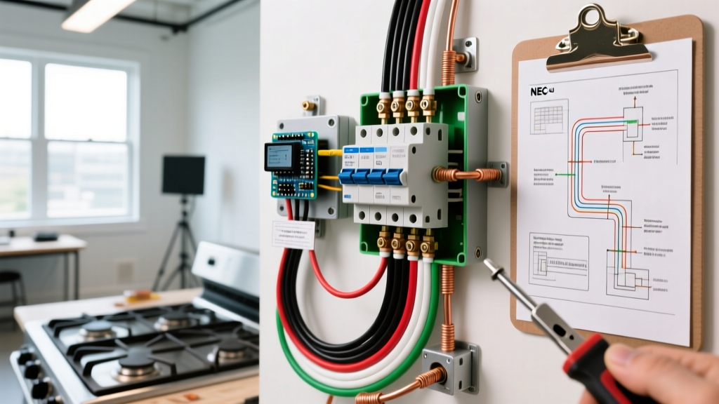
Today, the NEC mandates a dedicated 4-wire setup (Two Hots, One Neutral, One Ground). The neutral carries only the unbalanced 120V return current (for the stove's clock, lights, and control board), while the bare copper ground wire exclusively handles fault currents, ensuring the chassis never becomes energized during a failure.
Step-by-Step Safety & Termination Protocol
Properly wiring an electric stove requires more than just connecting colors to colors. The physical mechanics of the termination dictate the lifespan and safety of the circuit.
1. Lockout, Tagout, and Voltage Verification
Never rely on the breaker label. Shut off the main breaker or the specific 50-amp double-pole breaker, apply a physical lockout device, and test the bus bars with a CAT III or CAT IV rated multimeter (such as the Fluke 117) to confirm zero voltage before touching any conductors.
2. Precision Wire Stripping
Use a calibrated wire stripper like the Milwaukee 48-22-4108. Strip exactly the amount of insulation required by the breaker's lug depth—usually 5/8" to 3/4" for 6 AWG wire. Exposing too much bare copper leaves an uninsulated live gap inside the panel; stripping too little causes the lug to crush the insulation, leading to a high-resistance connection that will melt under load.
3. The Torque Specification Rule (NEC 110.14(D))
This is where most DIY fires start. NEC 110.14(D) requires that all electrical connections be torqued to the manufacturer's specifications using a calibrated torque tool.
- Tool Required: A calibrated torque screwdriver (e.g., Klein Tools 69165) or torque wrench.
- Typical Spec: For a 50-Amp Square D QO breaker terminating 6 AWG copper, the required torque is typically 45 inch-pounds. (Always read the label printed directly on the breaker).
- The Edge Case: Hand-tightening feels secure initially, but thermal expansion and contraction from the stove's heavy draw cycles will loosen an under-torqued screw within months, creating an arc fault. Over-torquing snaps the screw or strips the lug threads.
4. Aluminum Conductor Precautions
If your local code and budget dictate using 4 AWG aluminum wire instead of 6 AWG copper, you must apply an antioxidant compound (like Noalox) to the stripped aluminum before insertion. Aluminum oxidizes rapidly when exposed to air, creating a highly resistive layer that generates extreme heat. Furthermore, ensure your breaker lugs are explicitly rated for aluminum (marked AL or CU/AL).
Common Failure Modes in Stove Wiring
Even with the right materials, specific installation errors lead to catastrophic failures. Watch for these edge cases:
Double-Tapping the Breaker
Never connect the stove's 6 AWG wires to a breaker lug that already holds another circuit. Standard 50-amp breakers are not rated for double-tapping. If you are out of panel space, install a subpanel or use a breaker explicitly designed and listed for two conductors.
Improper Strain Relief on the Range Cord
When attaching the 4-prong pigtail to the back of the stove, the strain relief bracket must clamp down firmly on the thick outer jacket of the cord, not on the individual inner wires. If the jacket is not clamped, the weight of the cord will slowly pull the terminal spades out of the stove's block, causing a dead short against the metal back panel.
Neutral-to-Ground Bonding Inside the Appliance
Modern ranges ship with a bonding strap or wire connecting the neutral terminal to the chassis ground. This strap is only for legacy 3-prong installations. When wiring a 4-prong NEMA 14-50 setup, you must physically remove or disconnect this bonding strap inside the stove's terminal block. Leaving it connected in a 4-wire system causes neutral return current to flow on the bare ground wire, tripping GFCI/AFCI protection and violating NFPA 70 (NEC) grounding path rules.
Final Verification and Load Testing
Once the receptacle is mounted and the stove is plugged in, do not immediately turn on all burners. Follow this sequencing protocol:
- Restore power at the main panel and the 50-amp breaker.
- Use a receptacle tester (rated for 240V/50A) to verify correct phase rotation and ground continuity.
- Turn on the stove's control board and interior light (120V neutral test).
- Activate a single heating element to 450°F (240V hot leg test).
- After 15 minutes of operation, use an infrared thermal camera or non-contact IR thermometer to scan the breaker lugs and the receptacle face. Temperatures should not exceed ambient room temperature by more than 15°C (27°F). A hot breaker indicates a loose termination or a failing bus stab.
For comprehensive dimensional standards on the receptacles and plugs used in these high-amperage applications, refer to the ANSI/NEMA WD 6 Wiring Devices Dimensional Specifications. By treating a 50-amp stove circuit with the respect it demands—prioritizing torque specs, 4-wire grounding, and thermal management—you ensure a kitchen space that is both highly functional and fundamentally safe.