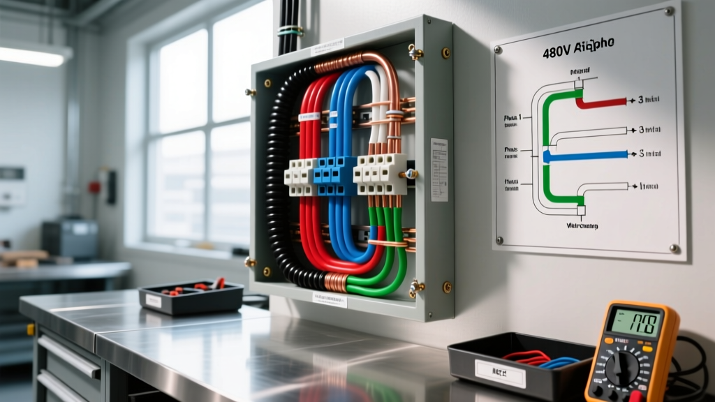

The Critical Role of Color Codes in 480V Troubleshooting
When diagnosing faults in commercial and industrial power systems, relying on an accurate electrical wiring color chart for 480V is not just a matter of code compliance—it is a critical life-safety measure. A 480V 3-phase system carries enough energy to sustain massive arc blasts and cause fatal electrocution. Unlike standard 120V residential circuits, where a reversed hot and neutral might simply trip a breaker or shock a user, a phase-to-phase fault on a 480V busbar can vaporize copper and cause catastrophic equipment failure.
Troubleshooting these systems requires a deep understanding of both National Electrical Code (NEC) mandates and deeply ingrained industry standards. This guide provides a comprehensive troubleshooting framework for identifying phases, tracing faults, and resolving color code anomalies in 480V environments.
NEC Mandates vs. Industry Standards: The Color Code Reality
A common point of confusion among junior electricians and maintenance technicians is the exact origin of 480V color codes. The NEC (specifically Article 215.12(C) in recent editions) requires that conductors be identified by phase and system, but it does not strictly mandate specific colors for 480V phases in the main text. Instead, it requires that the identification be consistent throughout the facility and documented.
However, to prevent the deadly mixing of 208V and 480V systems, the electrical industry and most local Authorities Having Jurisdiction (AHJs) have universally adopted a specific color schema. Understanding this distinction is vital when you are troubleshooting a panel and the colors do not match your expectations.
Standard 480V Wiring Color Chart
| System Type | Phase A (L1) | Phase B (L2) | Phase C (L3) | Neutral | Equipment Ground |
|---|---|---|---|---|---|
| 480Y/277V Wye | Brown | Orange | Yellow | Gray | Green / Bare |
| 480V Delta (Ungrounded) | Brown | Orange | Yellow | N/A | Green / Bare |
| 480V Corner-Grounded Delta | Brown | Orange | Yellow (w/ White Tape) | N/A | Green / Bare |
Note: In older legacy facilities, you may encounter Black, Red, and Blue used for 480V. Always verify voltage with a meter before assuming the system architecture based on legacy wire colors.
Common Troubleshooting Scenarios & Anomalies
When the physical wiring does not match the standard electrical wiring color chart for 480V, you are likely dealing with one of the following edge cases.
Scenario 1: The IEC vs. NEC Imported Machinery Clash
If you are troubleshooting a European-manufactured CNC machine, HVAC chiller, or industrial robot, the internal wiring will likely follow IEC 60446 standards rather than NEC/US conventions.
- IEC Phase Colors: Brown (L1), Black (L2), Gray (L3).
- The Hazard: An American technician expecting Orange for Phase B might misidentify the Black IEC wire as a neutral or ground, especially if the wire gauge is small. Connecting a 277V control circuit to an IEC Black (L2) phase will result in an immediate 480V phase-to-phase short.
- Troubleshooting Fix: Always trace the wiring back to the main disconnect and verify with a multimeter. Install permanent, engraved phenolic warning labels on the machine's main terminal block indicating 'IEC COLOR CODE - DO NOT ASSUME NEC'.
Scenario 2: The Corner-Grounded Delta Trap
Corner-grounded Delta systems are used in older industrial plants to provide 480V 3-phase power while allowing ground-fault detection on the remaining two phases. In this system, one phase is intentionally bonded to ground.
- The Anomaly: You measure Phase A to Ground (0V), Phase B to Ground (480V), and Phase C to Ground (480V).
- Troubleshooting Fix: The grounded phase should be identified with white or gray insulation, or marked with white/green tape at every termination point per NEC 250.36. If it is not marked, the system is out of code and highly dangerous. Do not use standard 3-pole breakers with ground-fault protection on these systems without verifying the breaker is specifically rated for corner-grounded delta applications (e.g., Schneider Electric PowerPact H-frame with specific ground-fault modules).
Step-by-Step Phase Verification and Fault Tracing
When a 480V motor fails to start, a VFD throws a phase-loss fault, or a transformer shows anomalous secondary voltages, follow this systematic troubleshooting flow.
- Don Appropriate PPE: Per NFPA 70E Table 130.5(C), working on exposed 480V parts typically requires a minimum of PPE Category 2 (8 cal/cm² arc-rated clothing, voltage-rated gloves with leather protectors, and an arc flash balaclava). Verify your glove test dates are within the last 6 months.
- Verify Meter Rating: Ensure your digital multimeter (DMM) is rated CAT IV 600V or CAT III 1000V. A standard CAT II meter can suffer an internal arc-over when measuring 480V busbars. The Fluke 87V or Fluke 289 are industry standards for this tier.
- Measure Phase-to-Ground (Wye Systems): Place one probe on the equipment grounding busbar and the other on each phase. You should read approximately 277V on all three phases. If one phase reads 0V and the others read 480V, you have a ground fault on that phase or are on a corner-grounded delta.
- Measure Phase-to-Phase: Measure A-B, B-C, and A-C. You should read 480V (±5%). A reading of 0V between two phases indicates a blown fuse, an open contactor, or a severed conductor upstream.
- Check Phase Rotation: Use a phase rotation meter (like the Amprobe PRM-6) at the motor starter load side. Reversed rotation will destroy scroll compressors and certain pump impellers instantly. Ensure the meter indicates A-B-C (or 1-2-3) clockwise rotation.
Essential Tools for 480V Troubleshooting
To effectively use the electrical wiring color chart for 480V in the field, you need tools that provide data beyond simple continuity.
Expert Tip: Never rely solely on visual color identification for lockout/tagout (LOTO). Always use a proximity tester followed by a direct-contact voltage detector to prove the absence of voltage. Color codes fade, get painted over, or were installed incorrectly by previous contractors.
- Fluke 1735 Three-Phase Power Logger: Essential for troubleshooting intermittent voltage sags on 480V feeders. It captures phase rotation, harmonics, and voltage dips over time, allowing you to correlate VFD faults with facility-wide power anomalies.
- Fluke T6-1000 Non-Contact Voltage Tester: Features FieldSense technology, allowing you to measure up to 1000V AC without metal-to-metal contact. Ideal for quickly verifying if a 480V disconnect is energized before opening the enclosure.
- Megger MIT485/2 Insulation Tester: When 480V motors trip on ground faults, use this to inject 1000V DC into the windings. A healthy 480V motor winding should read >100 Megohms. Readings below 2 Megohms indicate moisture ingress or failing varnish insulation.
Safety Boundaries and OSHA Compliance
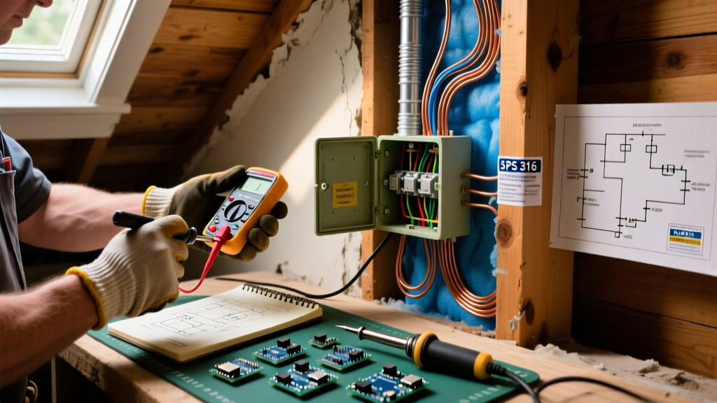
Troubleshooting 480V systems inherently involves exposed energized parts. The Occupational Safety and Health Administration (OSHA) strictly regulates these activities. According to OSHA electrical safety guidelines, only qualified persons may perform troubleshooting on energized 480V equipment.
For a standard 480V panelboard, the Limited Approach Boundary is typically 3 feet 6 inches, and the Restricted Approach Boundary is 12 inches. Crossing these boundaries without a documented energized electrical work permit, proper arc flash PPE, and insulated tools is a direct violation of federal safety regulations and facility insurance policies.
Summary
Mastering the electrical wiring color chart for 480V is about more than memorizing Brown, Orange, and Yellow. It requires an understanding of system topology (Wye vs. Delta), international standard clashes (IEC vs. NEC), and rigorous, meter-based verification. By combining strict adherence to NFPA 70E safety boundaries with high-category test equipment, electrical professionals can safely and efficiently diagnose faults in the most demanding commercial and industrial environments.