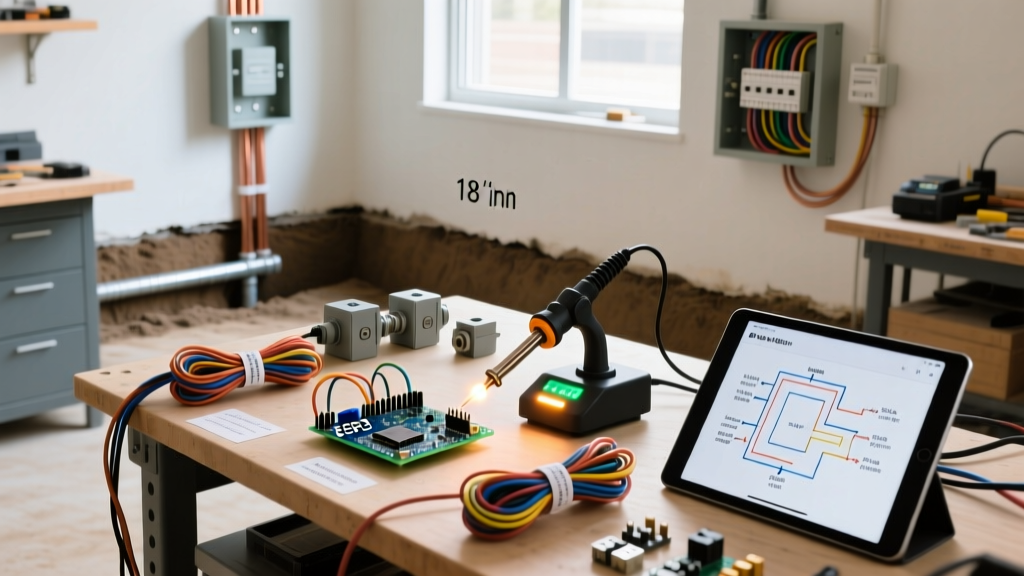

The Renovation Blueprint: Assessing Your Shed's Power Needs
Transitioning a backyard shed from simple storage into a fully functional woodworking or automotive workshop requires meticulous electrical planning. In 2026, the modern DIY workshop relies heavily on high-draw power tools, dust collection systems, and continuous-duty air compressors. Improperly planned shed electrical wiring doesn't just result in tripped breakers; it creates severe fire hazards and voltage drop issues that can destroy sensitive tool motors. Before you dig a single trench or mount a junction box, you must perform a rigorous NEC Article 220 load calculation tailored to your specific renovation goals.
Unlike a standard bedroom circuit, a workshop requires distinguishing between continuous loads (running for 3 hours or more, like lighting and dust collectors) and non-continuous motor loads. Motors require special consideration for startup surge, which can temporarily draw up to 300% of their running amperage. According to the National Fire Protection Association (NFPA 70), motor circuits must be sized to handle these inrush currents without nuisance tripping.
Workshop Load Calculation Matrix
Use the following matrix to map out your anticipated loads. This data assumes standard 120V/240V single-phase power typical in North American residential renovations.
| Equipment Type | Running Amps (120V) | Starting Surge (LRA) | Recommended Circuit |
|---|---|---|---|
| 10-inch Cabinet Table Saw | 15A | 45A | 20A Dedicated (12 AWG) |
| 2-Stage Air Compressor (60 Gal) | 18A (240V) | 55A (240V) | 30A Dedicated (10 AWG, 240V) |
| Cyclone Dust Collector (2 HP) | 12A | 36A | 20A Dedicated (12 AWG) |
| MIG Welder (140A Output) | 20A (240V) | 30A (240V) | 30A or 50A (10 or 6 AWG, 240V) |
| LED Shop Lighting (8 Fixtures) | 3A Total | N/A | 15A Shared (14 AWG) |
Feeder Cable Selection and Trenching Specs
The backbone of your shed electrical wiring is the underground feeder connecting your home's main panel to the shed's subpanel. For a modern workshop, a 60-amp subpanel is the absolute minimum recommended starting point, with 100-amp being the ideal future-proof standard. To deliver 60 amps over a standard 50-to-100-foot run while maintaining a voltage drop below 3%, you should pull 6 AWG Copper THWN-2 or 4 AWG Aluminum XHHW wire.
While direct-burial UF-B cable is an option, it is highly discouraged for workshop renovations due to its susceptibility to rodent damage and the difficulty of upgrading later. Instead, utilize conduit.
Trenching Depth and Conduit Requirements
- Conduit Type: 1.25-inch Schedule 40 PVC for the underground run, transitioning to Schedule 80 PVC where the conduit emerges from the ground and is subject to physical damage (up to 8 feet above grade).
- Burial Depth: NEC Table 300.5 mandates a minimum cover of 24 inches for rigid nonmetallic conduit (PVC) without GFCI protection on the feeder. If the feeder is GFCI protected at the source, you may reduce the depth to 18 inches, provided you install a warning ribbon 12 inches above the conduit.
- Pulling Compound: Always use a UL-listed wire pulling lubricant (like Polywater J) when pulling THWN-2 through PVC to prevent insulation scoring and reduce friction burn.
Code Alert: Under NEC Article 225.31, 225.32, and 225.33, a separate building supplied by a feeder must have a readily accessible disconnecting means. This can be satisfied by installing a main breaker in your shed's subpanel or a standalone exterior disconnect switch mounted directly adjacent to where the conduit enters the structure.
Subpanel Sizing and Grounding Electrode Systems
Selecting the right subpanel ensures you have adequate physical spaces for your circuits. A 60-amp feed should terminate in a panel with at least 12 to 16 spaces. The Square D HOM612L100PGC (Homeline 6-space, 12-circuit, 100A main lug) or the Siemens P2P1212L1100CU are excellent, cost-effective choices for 2026 renovations, typically retailing between $75 and $110.
The Critical Grounding Rule
One of the most frequent failure modes in shed electrical wiring is the improper bonding of neutral and ground. In a main panel, the neutral and ground bars are bonded. In a subpanel fed to a detached structure, they must remain strictly isolated. If you bond them at the subpanel, normal neutral return current will travel back to the main panel via both the ground wire and the neutral wire, energizing the grounding system and creating a lethal shock hazard.
Furthermore, per NEC Article 250.32, a detached shed with a subpanel requires its own Grounding Electrode System (GES). This typically involves driving two 5/8-inch by 8-foot copper-bonded ground rods into the earth. These rods must be spaced at least 6 feet apart and connected to the subpanel's ground bar using a continuous, unspliced 6 AWG bare copper wire. While the code allows a single rod if you can prove a ground resistance of less than 25 ohms using a fall-of-potential tester, most local inspectors will simply mandate the two-rod setup to bypass the testing requirement.
Interior Rough-In: Conduit, Boxes, and Circuit Mapping
Once the power is inside the shed, the interior rough-in begins. Because shed walls are often exposed or subject to impact from lumber and equipment, standard Romex (NM-B) cable stapled to studs is a poor choice. Exposed NM-B is prohibited by code in areas where it is subject to physical damage.
Why EMT Conduit is the Professional Standard
Electrical Metallic Tubing (EMT) is the gold standard for workshop interiors. It provides superior physical protection, acts as an equipment grounding conductor (when fittings are properly tightened), and allows for easy circuit upgrades in the future. For a standard renovation, use 1/2-inch EMT for 15A and 20A lighting and receptacle circuits, and 3/4-inch EMT for 240V tool circuits.
- Box Selection: Avoid shallow handy boxes. Use 4-inch square metal boxes with 1.5-inch raised device covers (mud rings). This provides over 21 cubic inches of wire fill capacity, making it significantly easier to terminate 12 AWG wires and pigtail GFCI connections.
- Receptacle Placement: NEC 210.52 requires receptacles to be placed so no point along the wall is more than 6 feet from an outlet. In a workshop, aim for a receptacle every 4 feet at workbench height (42 inches) and standard height (18 inches).
- GFCI Protection: All 125V, 15A and 20A receptacles in a shed must be GFCI protected. Use 20A TR (Tamper Resistant) WR (Weather Resistant) GFCI receptacles at the first outlet in the chain to protect downstream standard receptacles, saving space and money.
Lighting Design for Precision Work
Shed renovations often overlook lighting until the drywall is up. For woodworking and automotive tasks, you need a minimum of 50 foot-candles of illumination. Relying on a few bare bulbs will cast dangerous shadows over spinning saw blades.
Plan a dedicated 15A lighting circuit using 14 AWG THHN wire in your EMT conduit. Opt for 4000K to 5000K (Cool White/Daylight) LED wraparound fixtures or linear high-bays. The Lithonia Lighting 4500-Lumen LED Wraparound fixtures are a staple in 2026 workshop builds, providing wide-beam diffusion that minimizes harsh shadows. Mount these fixtures perpendicular to your primary workbenches to ensure light falls evenly across your workspace.
Common Failure Modes and Edge Cases
Even experienced DIYers make critical errors during shed electrical wiring projects. Avoid these specific edge cases:
- Voltage Drop on Long Runs: If your shed is more than 100 feet from the main panel, 6 AWG copper may experience a voltage drop exceeding 3% when running heavy inductive loads like air compressors. In these scenarios, upsize your feeder to 4 AWG copper or 2 AWG aluminum to maintain optimal tool performance and prevent motor burnout.
- Improper Lug Torquing: NEC 110.14(D) requires that all terminal connections be torqued to the manufacturer's specifications. Failing to use a calibrated torque screwdriver (like a CDI 40-200 in-lb model) on subpanel lugs and breaker terminals can lead to loose connections, arcing, and eventual panel fires.
- Moisture Ingress in Conduit: Underground conduit runs are prone to condensation and groundwater seepage. Always use duct seal putty to seal the ends of the conduit where it enters both the main house and the shed subpanel. This prevents moisture from migrating into your panels and causing corrosion on the bus bars.
Permitting and Inspection Checklist
Before energizing your new workshop, your shed electrical wiring must pass local inspections. The Occupational Safety and Health Administration (OSHA) and local AHJs (Authority Having Jurisdiction) strictly enforce grounding and GFCI mandates to prevent electrocution in damp, concrete-floored outbuildings. Prepare for your rough-in and final inspections by ensuring:
- Your trench is left open and uncovered for the inspector to measure depth.
- All conduit glue joints are fully seated and cured (wipe away excess PVC primer and cement).
- The neutral and ground bars in the subpanel are visibly isolated, and the main bonding screw or jumper strap has been removed.
- Both ground rods are driven flush with the earth or protected by a physical guard if left exposed, with the 6 AWG bare copper wire securely clamped using acorn-style ground rod clamps.
By approaching your shed electrical wiring with a comprehensive renovation plan, precise load calculations, and strict adherence to modern safety codes, you will build a workshop space that is not only highly functional but inherently safe for decades to come.