
The Hidden Culprits Behind Circuit Failures
When an electrical circuit fails, trips a breaker, or exhibits voltage drop, the immediate suspicion often falls on the primary components: the breaker, the receptacle, or the load. However, as any seasoned electrician knows, the root cause frequently lies in the unsung heroes of the electrical system: electrical wiring accessories. These include wire connectors, junction boxes, conduit fittings, strain reliefs, and cable staples. When these accessories degrade, are improperly installed, or are subjected to environmental stress, they introduce high-resistance connections, arc faults, and insulation failures.
In this comprehensive troubleshooting guide, we will dissect the most common failure modes of electrical wiring accessories. We will explore exact diagnostic procedures, reference specific product models, and provide actionable remediation steps aligned with the 2026 National Electrical Code (NEC) standards.
Diagnostic Matrix: Accessory Failure vs. Circuit Symptom
Before opening a single junction box, map your circuit symptoms to the likely accessory failure. Use the matrix below to narrow down your diagnostic focus.
| Circuit Symptom | Primary Suspect Accessory | Typical Failure Mode | Diagnostic Tool |
|---|---|---|---|
| Intermittent power loss, flickering lights | Twist-on Wire Connectors | Thermal expansion/contraction back-off | Infrared Thermal Camera |
| AFCI breaker tripping randomly | Push-in / Lever Connectors | Improper wire strip length causing micro-arcing | Multimeter (Continuity/Resistance) |
| Overheating at splice point, melted insulation | Junction Boxes / Enclosures | Box fill violation trapping thermal energy | Clamp Meter & Thermocouple |
| Ground fault (GFCI) tripping under load | Cable Staples / Strain Reliefs | Overdriven staple piercing NM-B ground insulation | Megger (Insulation Resistance Tester) |
Troubleshooting Wire Connectors: Nuts and Lever-Nuts
The 'Loose Nut' Arc Fault and Thermal Degradation
Twist-on wire connectors (wire nuts) remain a staple in North American wiring. However, they are highly susceptible to installation errors. A common failure mode occurs when solid and stranded wires are mixed without proper prep, or when the connector is under-torqued. According to UL 486A-486B standards, a properly installed wire nut must withstand a 20-pound pull force. If a connection feels loose or exhibits a voltage drop exceeding 0.5V under load, the internal spring has likely failed to bite into the copper.
Troubleshooting Step: Use an infrared thermal camera (such as the FLIR E8-XT) to scan the panel or junction box under a sustained 15A load. A temperature delta of more than 15°C (27°F) above ambient at the wire nut indicates a high-resistance connection. Replace failing standard connectors with premium models like the Ideal Industries Red #454 Wire-Nut, which features a deeper skirt and a more aggressive square-wire spring to prevent back-off during thermal cycling.
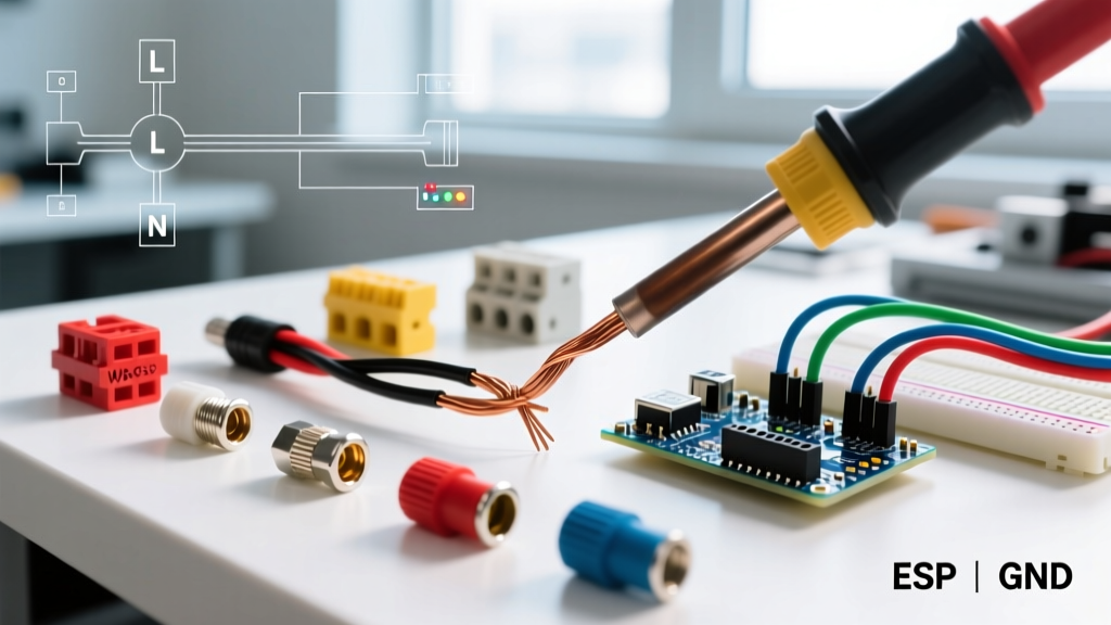
WAGO 221 Series Lever-Nut Installation Errors
Lever-nuts have revolutionized splicing, but they are not immune to user error. The WAGO 221-413 (3-conductor lever-nut) requires a precise wire strip length of 11mm (7/16 inch). As of 2026, bulk pricing for these connectors hovers around $0.75 per unit, making them cost-effective, but stripping the wire too short leaves the copper recessed, reducing the contact surface area. Stripping it too long leaves exposed copper outside the housing, creating a shock and short-circuit hazard.
Troubleshooting Step: If a WAGO connection is suspect, do not simply push the wire in further. Open the lever, extract the wire, and measure the strip length with a precision gauge. Inspect the copper for oxidation. If the wire was previously tinned with solder, WAGO explicitly advises against using their connectors, as solder cold-flows under the clamping pressure, leading to a loose connection over time. Re-strip the wire to bare copper and reseat.
Junction Box and Enclosure Anomalies
Box Fill Violations and Thermal Overload
Junction boxes do more than house splices; they act as thermal sinks and fire containment vessels. A frequent troubleshooting scenario involves a circuit that functions perfectly but trips a thermal-magnetic breaker prematurely, or wires that show signs of brittle, cracked insulation upon inspection. This is almost always a box fill violation.
The 2026 NEC Article 314.16 strictly dictates box volume based on the number and gauge of conductors. For example, a standard Carlon B618R old-work box (18 cubic inches) can legally hold a maximum of nine 14 AWG conductors. If an electrician forces twelve 14 AWG wires into this box, the cramped space prevents heat dissipation. The ambient temperature inside the box can easily exceed 60°C (140°F) under continuous load, degrading the PVC insulation of the THHN or NM-B cables.
Fix: Count every conductor, clamp, and device strap. If the box is overfilled, you must install a box extension ring or upgrade to a larger enclosure, such as a 4-square steel box with a mud ring, which provides up to 21 cubic inches of base volume.
Conduit Fitting and Knockout Leaks
In commercial and wet-location wiring, conduit fittings and locknuts are critical accessories. If moisture ingress is causing ground faults in an EMT (Electrical Metallic Tubing) run, the failure usually lies at the compression fittings or knockout seals. Standard set-screw connectors often fail to provide a watertight seal in damp environments.
Fix: Replace standard set-screw connectors with Appleton Squeeze-Tite or equivalent liquid-tight flexible metal conduit (LFMC) fittings. Ensure that unused knockouts are sealed with solid metal knockout seals (not plastic plugs, which degrade under UV exposure and temperature extremes), tightened with a locknut and sealed with a bead of silicone or duct seal compound.
Code Alert: The National Fire Protection Association (NFPA) consistently reports that loose connections and degraded splices are leading causes of residential electrical fires. Always verify that your wiring accessories carry a current UL or CSA listing for the specific environment (e.g., wet locations, plenum spaces) in which they are installed. For more on electrical fire statistics and prevention, refer to the Consumer Product Safety Commission (CPSC) Fire Safety Center.
Cable Management: Staples, Strain Reliefs, and Grommets
Insulation Piercing from Overdriven Staples
Cable staples are the most abused electrical wiring accessories. When securing 14/2 or 12/2 NM-B cable, installers often use a hammer and drive the staple flush or past-flush into the framing stud. A standard 1/2-inch crown staple (like the Gardner Bender MS-1025) driven too deeply will crush the PVC jacket and bite into the insulation of the inner conductors, particularly the bare ground wire, which sits in the center valley of the flat cable.
This creates a latent ground fault that may not trip the breaker immediately but will cause intermittent GFCI trips or shock hazards when the cable shifts due to structural settling or vibration.
Troubleshooting Step: Use an insulation resistance tester (Megger) set to 500V DC. Test between the ground wire and the hot/neutral conductors. A reading below 1 megohm indicates compromised insulation. To fix, cut out the damaged section, splice in a new length of NM-B using an accessible junction box, and secure the cable using insulated cable staples or stack-it nail plates, ensuring the staple rests gently on the jacket without compressing it.
Strain Relief Failures on Flexible Cords
For appliances and industrial equipment utilizing flexible cords, the strain relief connector (cord grip) is a vital accessory. If a cord is easily pulled out of a motor housing or control panel, the internal terminal block connections will eventually tear, causing an arc flash. The Heyco 1600 Series strain relief bushings are industry standards, but they must be matched exactly to the cable's outer diameter (OD). Using a 3/8-inch grip on a 5/16-inch cable will result in zero clamping force.
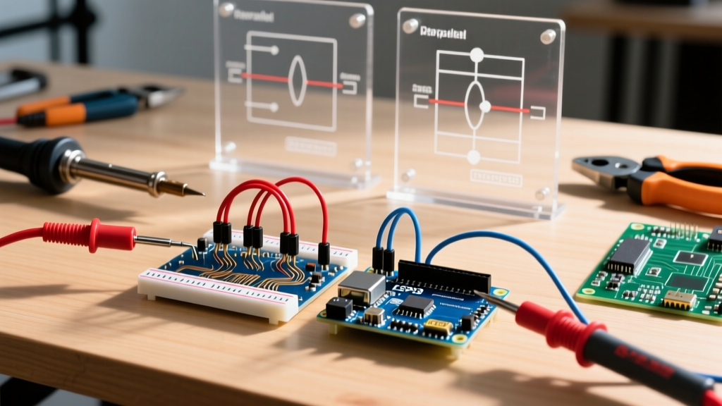
Step-by-Step Multimeter and Thermal Troubleshooting Workflow
When tracing a fault suspected to be caused by wiring accessories, follow this systematic workflow to ensure safety and accuracy:
- De-energize and Verify: Turn off the breaker and use a non-contact voltage tester (NCVT) followed by a CAT III or CAT IV digital multimeter (DMM) to confirm zero voltage at the accessory.
- Visual and Tactile Inspection: Gently tug on every wire entering a connector. Inspect junction boxes for scorch marks, melted plastic, or the distinct smell of ozone (indicative of micro-arcing).
- Resistance Testing: With the circuit de-energized, measure the resistance across the splice. A healthy accessory connection should read less than 0.5 ohms. Anything higher indicates oxidation or poor mechanical contact.
- Thermal Load Testing: Re-energize the circuit and apply the maximum expected load. Use an IR camera to monitor the accessories for 15 minutes. Document any hotspots exceeding a 15°C delta.
- Remediation and Documentation: Replace any failing accessories with UL-listed equivalents, ensuring proper torque and strip lengths. Update the panel schedule to reflect any changes in box fill or circuit routing.
Frequently Asked Questions
Can I use dielectric grease on wire nuts to prevent corrosion?
No. Standard twist-on wire nuts rely on the mechanical bite of the internal metal spring into the bare copper to maintain a low-resistance path. Applying dielectric grease (which is an insulator) can prevent the spring from making proper contact, increasing resistance and heat. If corrosion is a concern in damp locations, use connectors specifically rated for wet environments, or utilize WAGO lever-nuts which provide a gas-tight clamping connection that naturally excludes moisture.
Are push-in wire connectors reliable for high-vibration environments?
Standard push-in connectors (the kind without a release lever, often found on the back of receptacles) are not recommended for high-vibration environments like HVAC units or industrial machinery. Vibration can cause the internal brass grab-clip to fatigue and release the wire. For these applications, twist-on wire nuts secured with electrical tape, or WAGO 221 lever-nuts (which maintain constant spring pressure), are the required standard. For extreme vibration, crimp connectors are preferred. For more on industrial wiring standards, consult the National Electrical Manufacturers Association (NEMA) guidelines.
How do I fix a stripped knockout hole in a metal junction box?
If a knockout has been enlarged or stripped, a standard locknut will not secure the conduit fitting, compromising the grounding path and physical security. Use a knockout seal to close the hole, or install a reducing washer (e.g., from 1-inch to 3/4-inch) that spans the damaged knockout. Ensure the reducing washer is paired with a proper grounding locknut to maintain the equipment grounding conductor (EGC) continuity required by the NEC.