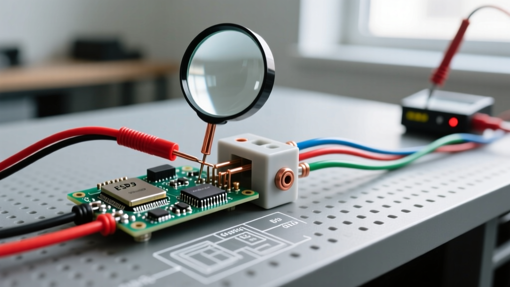

Mastering Single Phase Electrical Wiring Troubleshooting
Single phase electrical wiring is the backbone of residential and light commercial power distribution, typically delivering 120V/240V split-phase in North America or 230V in Europe and Asia. When these circuits fail, the symptoms can range from nuisance breaker trips to catastrophic equipment burnout. Troubleshooting single phase electrical wiring requires moving beyond simple continuity checks and understanding the physics of alternating current, impedance, and thermal degradation.
In this comprehensive 2026 troubleshooting guide, we dissect the most common failure modes in single phase systems, providing exact diagnostic workflows, mathematical formulas for voltage drop, and specific tool recommendations used by master electricians.
CRITICAL SAFETY WARNING: Before performing any invasive diagnostics, adhere to NFPA 70E and OSHA Electrical Safety standards. Always execute a Lockout/Tagout (LOTO) procedure, wear appropriate arc-flash PPE (minimum Category 1 for standard panel work), and verify zero energy state using a True-RMS meter on a known live source before testing the dead circuit.
Essential Diagnostic Arsenal
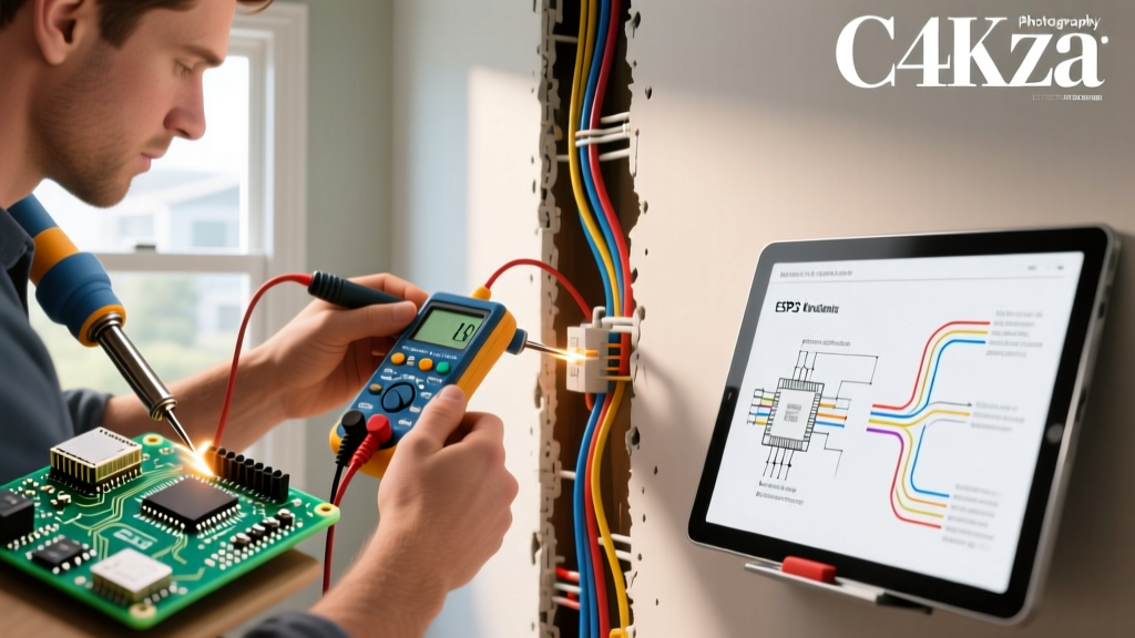
You cannot accurately troubleshoot modern single phase circuits with a basic $15 multimeter. Harmonic distortion from LED drivers and variable frequency drives (VFDs) will skew average-responding meters. Invest in the following calibrated tools:
- Fluke 117 True-RMS Multimeter (~$220): Features VoltAlert non-contact voltage detection and AutoVolt automatic AC/DC selection. Essential for identifying phantom voltages caused by capacitive coupling in long single phase cable runs.
- Klein Tools CL800 AC/DC Clamp Meter (~$135): Crucial for measuring neutral current imbalance and inrush currents on single phase motors without breaking the circuit.
- Fluke 1507 Insulation Resistance Tester (~$1,100): Mandatory for identifying micro-fractures in wire insulation that cause intermittent ground faults.
- Wiha 1000V Insulated Torque Screwdriver (~$85): Loose terminations are the number one cause of single phase thermal failures. Hand-tightening is no longer compliant with modern electrical codes.
Common Failure Modes & Diagnostic Matrix
Use this matrix to rapidly narrow down the root cause of single phase wiring faults based on initial field observations.
| Symptom | Probable Cause | Diagnostic Test | Expected / Target Reading |
|---|---|---|---|
| Dimming lights under load | Excessive voltage drop or loose neutral | Measure line-to-neutral voltage at panel, then at furthest receptacle under full load. | Less than 3% drop (max 3.6V on 120V circuit). |
| AFCI/GFCI nuisance tripping | Shared neutral, ground fault, or harmonic noise | Megger test line-to-ground; check neutral current vs ground current. | >1 Megohm insulation; 0A on equipment grounding conductor. |
| 240V appliance gets 120V | Open neutral on split-phase or lost pole | Measure Line 1 to Line 2 at main breaker lugs. | 240V ±5%. If 120V, utility or main breaker fault. |
| Burnt smell at receptacle | High-resistance termination / backstab failure | Thermal imaging (FLIR) or inspect wire striations and torque. | Terminations must meet manufacturer torque specs (e.g., 40 in-lbs). |
Deep Dive 1: Calculating and Fixing Voltage Drop
Voltage drop in single phase electrical wiring is often misdiagnosed as a failing appliance. The National Electrical Code (NEC) recommends a maximum 3% voltage drop for branch circuits and 5% for the combined feeder and branch circuit. While not strictly enforceable as a safety violation in all jurisdictions, exceeding these limits leads to motor overheating and reduced equipment lifespan.
The Single Phase Voltage Drop Formula
To calculate exact voltage drop, use the standard formula:
VD = (2 × K × I × D) / CM
- VD: Voltage Drop
- K: Direct current constant (12.9 ohms-cmil/ft for copper at 75°C)
- I: Load current in amperes
- D: One-way distance from source to load in feet
- CM: Circular mils of the conductor (12 AWG = 6,530; 10 AWG = 10,380)
Real-World Scenario: The 80-Foot Receptacle Run
Imagine a 120V single phase branch circuit wired with 12 AWG copper, supplying a 16A space heater located 80 feet from the panel.
VD = (2 × 12.9 × 16 × 80) / 6,530 = 5.06V
A 5.06V drop on a 120V circuit is a 4.2% drop. This exceeds the NEC 3% recommendation. The heater will receive only 114.9V, causing its internal blower motor to draw higher amperage to compensate, eventually tripping the thermal overload.
The Fix: Upsize the wiring to 10 AWG (CM = 10,380). Recalculating yields a 3.18V drop (2.6%), bringing the circuit into compliance and ensuring optimal appliance performance.
Deep Dive 2: The Multi-Wire Branch Circuit (MWBC) Open Neutral
One of the most dangerous faults in single phase electrical wiring is the open neutral on a Multi-Wire Branch Circuit (MWBC). An MWBC shares a single neutral conductor between two 120V hot legs (Line 1 and Line 2) that are on opposite phases, providing 240V potential between them.
The Physics of the Failure
If the shared neutral becomes disconnected (e.g., a loose wire nut in a junction box or a removed receptacle where the neutral was daisy-chained), the two 120V loads effectively become wired in series across 240V.
The voltage will divide inversely proportional to the resistance of the loads. If a 100W LED TV (high resistance) and a 1500W microwave (low resistance) are on the two halves of the MWBC, the TV could suddenly receive 200V+ while the microwave receives 40V. The TV's power supply will instantly detonate.
Diagnostic & Prevention Steps
- Test for Neutral Current: Clamp your Klein CL800 around the neutral wire in the panel. On a balanced MWBC, neutral current should be near 0A. If it equals the hot leg current, the opposite phase is disconnected.
- Verify Simultaneous Disconnect: The NFPA 70 (NEC) strictly requires MWBCs to have a simultaneous disconnecting means (a double-pole breaker or two single-pole breakers with an identified handle tie). If you find independent single-pole breakers without a tie, this is a critical code violation and a fire hazard.
- Pigtailing Rule: Never use a receptacle's internal terminal as the splice point for a neutral on an MWBC. Always use a WAGO 221-413 lever nut or equivalent wire connector to pigtail the neutral directly to the receptacle.
Deep Dive 3: Insulation Breakdown and Ground Faults
Intermittent ground faults in single phase wiring often evade standard multimeter testing because the fault only manifests under thermal stress or vibration. When a wire's PVC or THHN insulation degrades due to rodent damage, staple punctures, or prolonged heat exposure near recessed lighting, it creates a high-resistance path to ground.
Megger Testing Workflow
To isolate insulation breakdown, you must perform an Insulation Resistance (IR) test using a Megohmmeter.
- De-energize the circuit and remove all sensitive electronics (smart switches, LED drivers, AFCI breakers) to prevent high-voltage damage to solid-state components.
- Connect the Megger's positive lead to the hot conductor and the negative lead to the equipment grounding conductor (EGC).
- Apply 500V DC for 1 minute (standard for 600V rated building wire).
- Record the 1-minute IR value. According to industry standards referenced by groups like Penn State Extension and NETA, any reading below 1 Megohm indicates compromised insulation requiring immediate wire replacement.
The Hidden Culprit: Improper Termination Torque
A massive percentage of single phase wiring 'faults' are actually mechanical termination failures. As copper wire undergoes thermal cycling (heating under load, cooling when idle), it expands and contracts. If a breaker lug is not torqued to the manufacturer's exact specification, the wire will slowly work loose, increasing contact resistance. This generates intense localized heat, eventually melting the breaker casing or triggering an Arc Fault Circuit Interrupter (AFCI).
Manufacturer Torque Specifications (2026 Standards)
- Eaton BR Series: 40 in-lbs for 14-10 AWG; 45 in-lbs for 8 AWG.
- Square D QO / Homeline: 50 in-lbs for 14-4 AWG (always verify the label printed directly on the breaker casing).
- Siemens QT Series: 45 in-lbs for 14-10 AWG.
Always use a calibrated torque screwdriver. The era of the 'electrician's wrist' guessing the tightness is over, and modern AHJs (Authorities Having Jurisdiction) routinely inspect for properly torqued lugs in new construction and major remodels.
Summary: A Methodical Approach to Single Phase Systems
Troubleshooting single phase electrical wiring is an exercise in systematic elimination. By combining True-RMS voltage measurements, mathematical voltage drop analysis, MWBC physics, and precise mechanical torque, you can identify and resolve faults that elude less rigorous technicians. Always prioritize safety, adhere to the latest NEC guidelines, and document your Megger and voltage drop test results for future maintenance baseline comparisons.