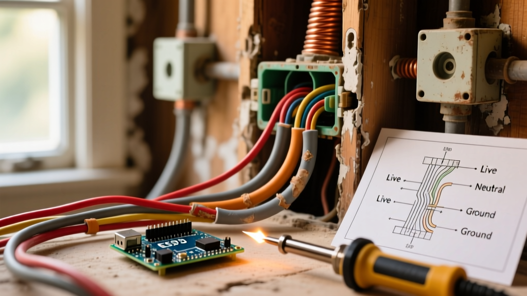

While copper remains the undisputed gold standard for residential and commercial electrical conductivity, it is not immune to failure. When troubleshooting copper wiring electrical systems, electricians and advanced DIYers must look beyond simple continuity checks. Failures in copper circuits rarely stem from the wire itself degrading; instead, they originate at the termination points, within the insulation, or due to modern supply chain anomalies. In 2026, with electrical loads increasing due to EV chargers and smart home infrastructure, the thermal and mechanical stresses on copper branch circuits are higher than ever.
The Physics of Copper Wiring Electrical Failures
To effectively troubleshoot, you must understand the material science of copper. Annealed copper boasts 100% IACS (International Annealed Copper Standard) conductivity, but its physical properties dictate how it behaves under load. Copper has a thermal expansion coefficient of approximately 16.5 µm/m·°C. When a 20-amp circuit powers a high-draw appliance like a space heater or EV Level 2 charger, the wire heats up and expands. When the load ceases, it cools and contracts.
Thermal Cycling and Terminal Creep
This constant expansion and contraction is known as thermal cycling. If the terminal screw securing the copper wire was not torqued to the manufacturer's exact specification, this cycling causes 'terminal creep.' Over 5 to 10 years, the screw backs out microscopically. This reduces the surface area of the mechanical connection, increasing contact resistance. According to Joule's first law (P = I²R), even a slight increase in resistance (R) generates exponential heat at the termination point, eventually leading to melted breaker lugs, arcing, or catastrophic fires.
The 2026 Supply Chain Issue: CCA vs. Solid Copper
A critical, often overlooked aspect of troubleshooting copper wiring electrical faults today is verifying that you are actually working with solid copper. The market has been flooded with Copper-Clad Aluminum (CCA) wire disguised as pure copper. CCA wire has a higher resistance and is significantly more brittle. If you torque CCA wire to standard copper specifications, the aluminum core will crush and 'cold flow,' resulting in a loose connection within months. Always scrape the edge of the conductor with a utility knife before troubleshooting; if you see a silver-white core beneath a copper veneer, you are dealing with CCA, and the entire branch circuit must be evaluated for voltage drop and replaced.
Diagnostic Toolkit for Copper Circuit Troubleshooting
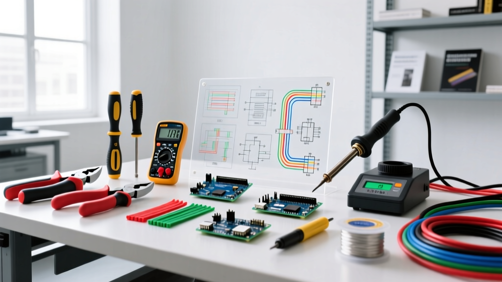
Accurate diagnosis requires precision instruments. Guesswork leads to misdiagnosed breakers and unnecessary drywall demolition. Below is the essential 2026 diagnostic toolkit for copper circuit analysis.
| Tool Category | Recommended Model (2026) | Primary Diagnostic Purpose | Approx. Cost |
|---|---|---|---|
| True-RMS Multimeter | Fluke 87V Industrial | Measuring exact voltage drop under load to the hundredth of a volt. | $475.00 |
| Thermal Imager | FLIR E8-XT | Identifying high-resistance hotspots at breaker lugs and receptacles. | $1,150.00 |
| Torque Screwdriver | Milwaukee 48-22-7110 | Verifying and correcting terminal torque to NEC 110.14(D) specs. | $140.00 |
| Wire Stripper/Gauger | Klein Tools 11063W | Verifying AWG size to rule out undersized wire on high-amp breakers. | $32.00 |
Step-by-Step Troubleshooting: Voltage Drop and High Resistance
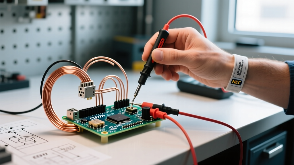
Voltage drop is the most common symptom of a failing copper wiring electrical connection. The Fluke guide on voltage drop testing emphasizes that testing must always be done under a loaded condition. An open circuit with high resistance will still read 120V on a digital multimeter due to the meter's high impedance.
- Establish Baseline Voltage: With no load on the circuit, measure the voltage at the panel breaker terminal and then at the furthest receptacle. Note the difference.
- Apply a Known Load: Plug in a resistive load tester (such as a 1500W hair dryer or a dedicated 15A load bank) at the furthest receptacle. This should draw approximately 12.5 amps on a 120V circuit.
- Measure Loaded Voltage: While the load is running, measure the voltage at the receptacle. According to NEC guidelines, the voltage drop on a branch circuit should not exceed 3% (3.6V on a 120V system). If your drop exceeds 5%, you have a high-resistance fault.
- Isolate the Fault: Move your multimeter probes to intermediate junction boxes and receptacles. The segment of the circuit where the voltage suddenly drops is where your high-resistance fault (loose wire nut, backstabbed receptacle, or corroded lug) is located.
- Thermal Verification: With the load still running, scan the suspected termination points with a thermal imager. A delta-T (temperature difference) of more than 15°C between the wire insulation and the breaker terminal confirms a failing mechanical connection.
Troubleshooting Matrix: Symptom to Solution
Use this matrix to quickly correlate field symptoms with underlying copper wiring faults.
| Field Symptom | Probable Root Cause | Diagnostic Test | Corrective Action |
|---|---|---|---|
| Breaker trips immediately upon load application | Dead short (hot to ground or neutral) or undersized AWG wire. | Megohmmeter (Megger) test at 250V to check insulation breakdown. | Locate staple puncture or nail damage; replace damaged cable segment. |
| Flickering lights on the same circuit when an appliance cycles | Loose neutral connection at the panel or a backstabbed receptacle. | Measure voltage between Hot and Neutral, then Hot to Ground under load. | Migrate all backstabbed connections to side-terminal screw connections. |
| Discolored or melted receptacle faceplate | High resistance due to thermal creep or using a 15A receptacle on a 20A circuit. | Visual inspection and thermal imaging under load. | Replace receptacle with a 20A commercial-grade spec grade model; torque to 14 in-lbs. |
| Arc Fault Breaker (AFCI) nuisance tripping | Shared neutrals, damaged insulation, or loose wire nut arcing. | Use AFCI diagnostic tool to read the specific fault signature (arc vs. ground). | Check all multi-wire branch circuits (MWBC) for handle ties and isolated neutrals. |
NEC Torque Specifications: The 2026 Enforcement Reality
The National Fire Protection Association (NFPA) NEC guidelines have drastically tightened termination requirements. NEC Article 110.14(D) mandates that all terminations rated 100 amps or less must be tightened using a calibrated torque tool. In 2026, local Authorities Having Jurisdiction (AHJs) are routinely rejecting rough-in and final inspections if torque seal (a brightly colored wax marker) is not visible on breaker lugs. Hand-tightening copper wiring electrical terminations with a standard screwdriver is no longer code-compliant or safe.
Expert Warning: Never use an impact driver or a standard VDE insulated screwdriver to torque breaker lugs. The sudden rotational force can snap the terminal screw or strip the aluminum bus bar threads inside the panel, requiring a complete panel replacement costing upwards of $2,500.
Standard Torque Specifications for Copper Terminals
Always defer to the manufacturer's label inside the panel door, but these are the baseline specifications for standard residential load centers (e.g., Square D QO, Siemens QT, Eaton BR):
| Breaker Amperage | Copper Wire Gauge (AWG) | Typical Torque Requirement |
|---|---|---|
| 15A - 20A | #14 to #10 AWG Solid/Stranded | 20 to 25 in-lbs |
| 30A - 40A | #10 to #8 AWG Solid/Stranded | 30 to 35 in-lbs |
| 50A - 60A | #6 to #4 AWG Stranded | 40 to 45 in-lbs |
| 100A (Main Lug) | #3 to #1/0 AWG Stranded | 150 to 200 in-lbs |
Frequently Asked Questions
Can I mix solid and stranded copper wire in the same wire nut?
Yes, but it requires a specific technique. Stranded wire tends to wrap around solid wire, leaving the stranded copper exposed below the wire nut, which can cause a short. When pigtailing solid and stranded copper wiring electrical conductors, strip the stranded wire 1/16th of an inch longer than the solid wire. Hold them flush and twist the wire nut on tightly. For maximum reliability in 2026, use WAGO 221 lever-nuts, which independently clamp solid and stranded conductors with perfect, maintenance-free pressure.
Why is my copper wire turning green inside the panel?
Green or white powdery corrosion on copper wire is copper oxide or copper carbonate, usually caused by high humidity, galvanic corrosion (if in contact with dissimilar metals like aluminum or steel without an inhibitor), or exposure to sulfur compounds. While surface oxidation on the bare ground wire is harmless, oxidation creeping under the insulation of the hot or neutral conductors increases resistance. Clean the exposed conductors with a Scotch-Brite pad and apply an antioxidant compound like Noalox if your local OSHA electrical safety standards or local AHJ requires it for specific damp environments.
How do I test for a broken copper wire inside a wall without cutting drywall?
Use a Time Domain Reflectometer (TDR) or an advanced tone-and-probe kit with a capacitance meter. By measuring the capacitance of the open circuit, you can calculate the exact distance to the break. Standard AWG 12/2 Romex has a capacitance of roughly 25 picofarads per foot. If your meter reads 250 pF on an open hot wire, the break is exactly 10 feet from your testing point, allowing you to open the drywall with surgical precision.