
When it comes to aviation, electrical failures are not merely an inconvenience; they are a critical safety hazard that can lead to in-flight fires or total avionics blackout. Proper aircraft electrical wiring demands a rigorous adherence to military and federal aviation standards that far exceed typical residential or automotive codes. As of 2026, the proliferation of high-draw EFIS (Electronic Flight Information System) glass panels, electrically actuated landing gear, and composite airframes in both certified and experimental aircraft makes strict adherence to wiring codes more vital than ever.
Whether you are restoring a classic Cessna, building an experimental Van's RV, or maintaining a commercial fleet, understanding the regulatory framework and physical standards of aerospace wiring is non-negotiable. This guide breaks down the core codes, MIL-SPEC wire nomenclature, routing matrices, and termination standards that govern aircraft electrical systems.
The Core Regulatory Framework: FAA and SAE Standards
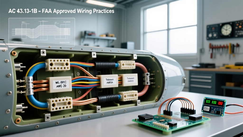
Unlike home wiring governed by the NEC (National Electrical Code), aviation wiring in the United States is primarily dictated by the Federal Aviation Administration (FAA) and SAE International. The foundational text for any mechanic or experimental builder is FAA Advisory Circular 43.13-1B (Acceptable Methods, Techniques, and Practices – Aircraft Inspection and Repair). Chapter 11 of this document specifically details acceptable wiring practices.
For original equipment manufacturers (OEMs) and advanced aerospace engineering, the governing standard is SAE AS50881 (Wiring Aerospace Vehicle). While experimental builders under FAR Part 21.191 are not strictly legally bound to AS50881, adopting its rigorous methodologies for wire derating, bundle sizing, and arc-tracking prevention is considered the gold standard for ensuring passenger safety and passing Designated Airworthiness Representative (DAR) inspections.
Key Directives to Memorize
- FAA AC 43.13-1B, Chapter 11: Covers wire selection, routing, splicing, and termination for general aviation.
- FAA AC 43.13-2B: Focuses on acceptable alterations, including the installation of modern avionics and circuit protection.
- MIL-W-22759 & MIL-C-27500: The baseline military specifications for single-conductor and multi-conductor shielded aerospace cables.
MIL-SPEC Wire Selection: Decoding the Nomenclature
Never use standard PVC-insulated wire (like THHN or automotive GXL) in an aircraft. PVC melts at relatively low temperatures, degrades under UV exposure, and emits highly toxic hydrochloric gas when it burns. Instead, aircraft electrical wiring relies on PTFE, ETFE (Tefzel), or Polyimide (Kapton) insulations.
Critical Safety Warning: Early generation MIL-W-81381 Polyimide (Kapton) wire was notorious for hydrolytic degradation, leading to micro-cracking and catastrophic arc-tracking fires. The FAA issued multiple Airworthiness Directives (ADs) mandating its removal. Always specify modern ETFE or PTFE wire for new installations.
Aerospace wire is identified by a complex MIL-SPEC nomenclature. Let's decode the most common single-conductor wire used in modern general aviation: M22759/16-22-9.
- M22759: The base military specification for insulated electrical wire.
- /16: The 'slash sheet' number indicating ETFE (Tefzel) insulation, rated for 150°C and 600V.
- 22: The American Wire Gauge (AWG) size.
- 9: The color code (9 = White, 0 = Black, 2 = Red, 6 = Blue).
Wire Insulation Comparison Matrix
| Specification | Insulation Material | Temp Rating | Weight | Avg. Cost (2026) | Best Application |
|---|---|---|---|---|---|
| M22759/16 | ETFE (Tefzel) | 150°C | Standard | $1.20 - $1.80 / ft | General airframe wiring, avionics buses |
| M22759/32 | PTFE / PI / PTFE | 200°C | Lightweight | $2.50 - $3.50 / ft | Engine compartments, high-temp zones |
| M22759/44 | Cross-linked ETFE | 150°C | Ultra-Light | $1.80 - $2.20 / ft | Weight-critical experimental builds |
| Spec 55 (Raychem) | Modified ETFE | 150°C | Standard | $1.50 - $2.00 / ft | Commercial OEM equivalent to /16 |
Routing, Separation, and Chafing Prevention
Routing aircraft electrical wiring requires a strategic approach to prevent electromagnetic interference (EMI), chafing, and catastrophic interaction with aircraft systems. FAA AC 43.13-2B outlines strict minimum separation distances between wire bundles and other airframe components.
Minimum Separation Distance Matrix
| Airframe Component | Minimum Separation | Required Protection if Separation is Impossible |
|---|---|---|
| Fuel Lines (Flammable Fluids) | 6.0 inches | Route wire ABOVE the line; use Teflon tubing sleeving and clamp securely. |
| Flight Control Cables | 2.0 inches | Install mechanical stops or pulley guards to prevent cable slap against wires. |
| Hot Exhaust / Engine Components | 12.0 inches | Use high-temp PTFE wire (M22759/32) and fire-resistant braided sleeving. |
| Oxygen Lines | 2.0 inches | Ensure no splices exist in the bundle; use continuous runs only. |
| Magnetic Compass / Flux Valve | 12.0 to 36.0 inches | Use twisted-pair shielded cables to cancel electromagnetic fields. |
Chafing Prevention: Whenever a wire bundle passes through a metal bulkhead or rib, it must be protected. The standard practice is to install a rubber grommet (MS35650 series) or use a dedicated pass-through hole with a chamfered edge, secured with MIL-SPEC cable ties (MS3367) and cushioned with edge protection tape.
Termination and Crimping Standards
Soldering is largely prohibited in modern aerospace wiring for primary connections. Solder wicks up into the wire strands under capillary action, creating a stiff, brittle point just outside the solder joint that is highly susceptible to vibration-induced fatigue and breakage. Instead, gas-tight mechanical crimping is the mandated standard.
The Crimping Ecosystem
To achieve a MIL-SPEC crimp, you cannot use standard automotive ratcheting crimpers. You must use precision indent crimp tools calibrated to the specific terminal and wire gauge. The industry standard for general aviation and experimental builders is the Daniels Manufacturing Corp (DMC) AFM8 or the M22520/2-01 crimp tool.
- Strip Length: Use a precision thermal wire stripper (like the Teledyne Reynolds ST-500) or a high-quality mechanical stripper (Ideal 45-101) to avoid nicking the copper strands. Nicked strands reduce tensile strength and create hot spots.
- Tool Setting: Set the rotary selector dial on the DMC AFM8 to the exact setting specified by the terminal manufacturer (e.g., a setting of '4' for 22 AWG wire using an M39029/5-115 pin).
- Visual Inspection: The wire strands must be visible in the inspection hole of the terminal barrel, and the insulation must not be crimped inside the conductor barrel.
- Tensile Pull Test: A proper MIL-SPEC crimp will cold-weld the metal. For 22 AWG wire, the crimp must withstand a minimum pull-test force of 15 pounds without the wire slipping or breaking. For 12 AWG wire, the requirement jumps to 50 pounds.
Voltage Drop Calculations in Avionics
Aircraft operate on 14V or 28V DC systems. Because the voltage is relatively low, voltage drop over long wire runs (such as from the alternator to the main bus, or from the battery to the starter contactor) can severely degrade avionics performance and cause nuisance circuit breaker trips.
The FAA recommends a maximum voltage drop of 0.5 volts for continuous duty circuits and 1.0 volt for intermittent duty circuits (like landing gear motors or flap actuators).
Calculation Formula:
VD = (2 × L × R × I) / 1000
(Where VD = Voltage Drop, L = One-way wire length in feet, R = Wire resistance per 1000 ft, I = Current in Amps).
Real-World Example: Running a 10-amp avionics master circuit 15 feet from the bus using 18 AWG wire (Resistance = 6.385 ohms/1000ft).
VD = (2 × 15 × 6.385 × 10) / 1000 = 1.91 Volts.
This exceeds the 0.5V limit. The builder must step up to 14 AWG wire (Resistance = 2.525 ohms/1000ft) to achieve a safe voltage drop of 0.75V, or ideally 12 AWG for a drop of 0.47V.
Circuit Protection: Breakers vs. Fuses
Overcurrent protection in aircraft electrical wiring must be both reliable and resettable in flight where appropriate. Circuit protection devices must meet MIL-PRF-8805 or SAE AS39029 standards.
- Circuit Breakers: Used for circuits that may need to be reset in flight (e.g., avionics, pitot heat, fuel pumps). Popular brands include Heinemann (Eaton) and Tyco. They must be 'trip-free' meaning the internal thermal mechanism will trip even if the pilot physically holds the toggle in the ON position during a short circuit.
- Fuses: Used for circuits that should NOT be reset in flight without troubleshooting, or for high-amperage main feeder lines (e.g., main alternator output, battery master). ANL or FHL current limiters are standard for 50A to 300A main bus protection.
Frequently Asked Questions (FAQ)
Can I use automotive wire in my experimental aircraft?
While the FAA does not explicitly ban automotive wire (like SXL) in experimental amateur-built aircraft under Part 21.191, using it is highly discouraged by DARs and aviation insurance underwriters. Automotive wire insulation is not rated for the extreme temperature swings, altitude-induced outgassing, and vibration profiles of flight. Sticking to MIL-W-22759 ETFE wire ensures insurability and long-term safety.
Do I need to shield all my wiring?
No. Shielding adds significant weight and complexity. Unshielded wire (M22759/16) is perfectly acceptable for power distribution, lighting, and basic switches. However, shielded wire (MIL-C-27500) or twisted-pair shielding is mandatory for sensitive data buses (RS-232, ARINC 429, CAN bus), audio panels, and encoder connections to prevent EMI from alternator whine or ignition harnesses.
How often should aircraft wiring be inspected?
For certified aircraft, wiring is inspected during the annual or 100-hour inspection per the manufacturer's maintenance manual. For older aircraft (over 20 years), a dedicated Electrical Wiring Interconnection System (EWIS) inspection is recommended to check for brittle insulation, corroded crimps, and bundle chafing, particularly in the wheel wells and engine nacelles.