
Mastering the Blueprint: Troubleshooting With an Electrical Wiring House Diagram
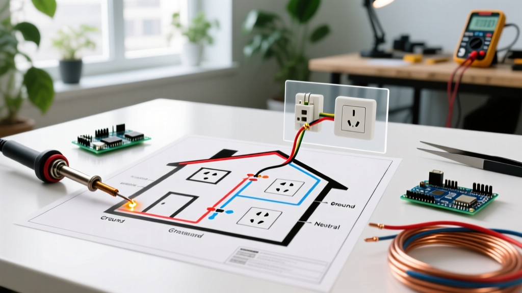
When a circuit fails, guesswork is the most expensive tool in your arsenal. Randomly opening junction boxes or replacing breakers wastes time and introduces new hazards. The most efficient way to isolate a fault is by consulting an electrical wiring house diagram. Whether you are dealing with a legacy 1970s build or a modern 2026 smart-home installation equipped with SPAN.IO panels, the foundational schematic remains your ultimate diagnostic map.
A proper diagram transitions you from reactive part-swapping to methodical fault isolation. In this guide, we will decode residential schematic symbology, establish a step-by-step diagnostic workflow, and explore real-world failure modes that only a wiring diagram can help you pinpoint.
Decoding the Symbology of an Electrical Wiring House Diagram
Before you uncap a single wire nut, you must understand the language of the schematic. Residential diagrams use standardized ANSI and IEEE symbols to represent components, but their troubleshooting implications are rarely explained in standard legends.
| Symbol / Notation | Component | Troubleshooting Insight & Edge Cases |
|---|---|---|
| Circle with 'G' or 'GFCI' | Ground Fault Circuit Interrupter | If downstream nodes are dead, the fault is likely a reversed LINE/LOAD wiring error or a tripped internal relay, not a bad breaker. |
| Two switches linked by 3 lines | 3-Way Switch Setup | Indicates traveler conductors. If the light only works in one switch position, the diagram helps identify if the 'common' terminal was miswired during a previous remodel. |
| Split Circle / Dual Hot Notation | Multi-Wire Branch Circuit (MWBC) | Shows a shared neutral. If testing reveals 240V across a 120V receptacle, the diagram confirms if the two hots are incorrectly landed on the same phase leg. |
| Straight line with diagonal hash | Switch Loop (Power to Light) | Indicates the white wire is being used as a hot return. Per NEC 404.2(C), modern diagrams will show a 3-wire cable to provide a neutral at the switch box. |
Step-by-Step Troubleshooting Workflow
Follow this systematic approach to leverage your electrical wiring house diagram for safe and accurate diagnostics.
- Isolate the Circuit Topology: Locate the circuit on the diagram and trace it from the panel schedule to the furthest node. Determine if the circuit is a radial daisy-chain, a star topology (home-run to a central junction box), or a complex series-parallel hybrid.
- Identify the Power Source Entry Point: Does the power hit the switch first, or the light fixture first? This fundamentally changes how you use your multimeter. If power hits the light first (a switch loop), the switch box will only have two wires (pre-2011) or three wires (post-2011 NEC updates), and you will not find a continuous neutral to test against.
- Map the Daisy-Chain Nodes: Mark the halfway point of the circuit on the diagram. Test a receptacle at this midpoint. If it is live, the fault is downstream. If it is dead, the fault is upstream or at the node itself. This binary search method cuts your physical tracing time by 50%.
Common Residential Wiring Faults & Diagram-Based Diagnostics
Scenario A: The 'Dead Downstream' Daisy-Chain Failure
The Symptom: A bedroom receptacle is dead, but the breaker is not tripped.
The Diagram Insight: Your electrical wiring house diagram shows this receptacle is the third in a series of five on a 15-amp branch circuit. The receptacle physically upstream of it (Node 2) is functioning.
The Diagnosis: The failure is almost certainly at Node 2. Builders and hasty DIYers frequently use push-in 'backstab' terminals instead of screw terminals. These spring-loaded contacts lose tension over time, especially under thermal cycling from high-draw loads like space heaters. The vibration from a vacuum cleaner can also shake a loose backstab connection free.
The Fix: Open Node 2. Remove the backstabbed wires. Strip them back to clean copper and terminate them using the side screw terminals. For a 2026-compliant repair, use a torque screwdriver (like the Klein Tools 69000) set to the manufacturer's specification—typically 14 in-lbs for standard 15A Leviton or Eaton receptacles. This prevents terminal overheating and satisfies NEC 110.14(D) requirements.
Scenario B: The Phantom Neutral in an MWBC
The Symptom: A homeowner replaces a home office receptacle and suddenly their $2,000 gaming PC power supply blows, or a lamp burns incredibly bright before popping the bulb.
The Diagram Insight: The schematic reveals a Multi-Wire Branch Circuit (MWBC) serving the office and the adjacent bedroom, sharing a single 12 AWG white neutral wire back to the panel.
The Diagnosis: During the receptacle replacement, the installer likely broke the brass fin (hot-side tab) on the new receptacle without realizing the circuit was an MWBC, or they disconnected the shared neutral while the circuit was still energized. If the neutral is severed while both 120V legs are drawing current, the two circuits form a 240V series loop, sending overvoltage to the lighter load.
The Fix: Restore the neutral continuity. Crucially, verify the panel breaker configuration. As mandated by the NFPA 70 National Electrical Code, MWBCs must be protected by a 2-pole breaker or two single-pole breakers with an identified handle-tie (NEC 210.4 and 240.15(B)(1)). This ensures both legs are de-energized simultaneously during future maintenance.
Scenario C: The 3-Way Switch Traveler Confusion
The Symptom: A hallway light controlled by two switches only turns on when Switch A is in the 'up' position. If Switch A is down, Switch B does nothing.
The Diagram Insight: The diagram shows a standard 3-way setup with a 14/3 cable running between the switches, containing one black (hot), one white (traveler), and one red (traveler).
The Diagnosis: A previous handyman likely replaced Switch A and failed to identify the 'Common' terminal (usually the dark-colored screw). They wired the constant hot to a traveler terminal, and a traveler to the common. This locks the circuit logic, requiring Switch A to bridge the correct path before Switch B can function.
The Fix: Use a non-contact voltage tester (NCVT) to find the single always-hot wire at Switch A with the circuit energized. Turn the power off, and land that specific wire on the black 'Common' screw of the new 3-way switch (e.g., Eaton 1733-7W).
Modern Diagnostic Tools to Complement Your Diagram
While the electrical wiring house diagram provides the logic, modern 2026 diagnostic tools provide the physical verification. Relying solely on a cheap neon tester is a recipe for misdiagnosis due to phantom voltages.
- Fluke 117 True-RMS Multimeter (~$220): Essential for measuring exact voltage drops. A reading of 114V at the panel but 102V at the receptacle indicates a high-resistance fault (like a corroded wire nut) somewhere along the diagram's path.
- Milwaukee 2446-20 M12 Thermal Imager (~$350): If your diagram shows a junction box buried behind drywall, a thermal imager can detect the heat signature of a failing, high-resistance connection through the wall before it becomes a fire hazard.
- Klein Tools ET910 Circuit Finder (~$60): When the as-built diagram is missing or inaccurate, this tool uses signal injection to map the physical circuit, allowing you to draw your own accurate schematic before beginning repairs.
Safety Protocols & NEC Compliance
Never troubleshoot a live circuit without proper PPE and training. According to OSHA Electrical Safety Guidelines, arc flash and shock hazards remain a leading cause of severe injury in residential and commercial maintenance.
Pro-Tip for Smart Panels: If your home is equipped with a modern smart panel (like Leviton Smart Load Center or SPAN), the accompanying app provides a digital, real-time electrical wiring house diagram. However, smart breakers only tell you if the circuit is tripped or drawing current; they cannot diagnose an open neutral or a reversed hot/load condition. Physical tracing and multimeter testing remain mandatory for deep diagnostics.
Always verify your tools against a known live source before and after testing a dead circuit (the Live-Dead-Live test method). For further reading on safe testing procedures and residential wiring standards, consult the Fluke Electrical Testing Resources library. By combining a thorough understanding of your wiring diagram with methodical testing and modern tools, you can resolve complex electrical faults safely, efficiently, and to code.