
The Evolution of Switch Leg Electrical Wiring
If you are upgrading a light fixture or installing a smart home system in 2026, understanding switch leg electrical wiring is no longer optional—it is a critical safety and functionality requirement. Historically, electricians referred to this as a 'switch loop.' In older homes, power was routed to the ceiling light fixture first, and a single 2-wire cable was dropped down to the wall switch. While this method worked for simple mechanical toggles, it created a massive hurdle for the modern smart home era.
Today, the landscape of residential wiring has fundamentally shifted. Smart switches, dimmers with LED drivers, and motion sensors require a constant trickle of power to operate their internal Wi-Fi, Zigbee, or Z-Wave radios. Without a dedicated neutral wire at the switch box, these devices will flicker, fail to connect, or cause 'ghosting' in LED bulbs. This guide breaks down the modern code requirements, material costs, and step-by-step installation procedures for routing a compliant, future-proof switch leg.
NEC 404.2(C) and the Neutral Wire Mandate
The most significant change to switch leg electrical wiring in the last two decades is the enforcement of NEC 404.2(C). The National Electrical Code now explicitly requires that a neutral (grounded) conductor be present at every wall switch box controlling lighting loads.
Code Insight: According to the National Fire Protection Association (NFPA), the 2011 NEC revision first introduced the neutral requirement, and subsequent 2023 and 2026 code cycles have strictly enforced it for all new construction and major remodels. You can no longer use 14/2 or 12/2 NM-B cable for a new switch leg dropped from a ceiling box.
To comply, you must use a 3-wire cable (14/3 or 12/3, depending on the circuit amperage). This provides a dedicated line (hot), a dedicated load (switched hot), and the mandatory neutral, ensuring your switch box is ready for any technology you install today or in the future.
2026 Material & Tool Cost Matrix
Before pulling wire, you need the right materials. Using outdated connectors or undersized wire will lead to voltage drop and failed inspections. Below is a breakdown of current market pricing and recommended professional-grade materials for a standard 15-Amp lighting circuit.
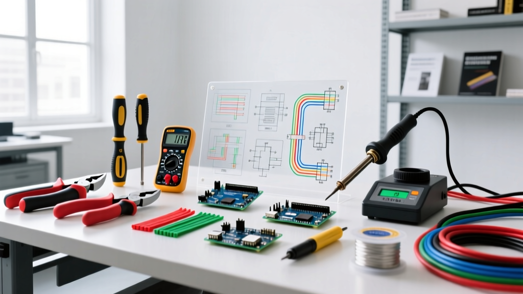
| Category | Recommended Product | Specs / Details | Est. 2026 Cost |
|---|---|---|---|
| Cable | Southwire Romex SIMpull 14/3 | 14 AWG, 3-Conductor with Ground, 250ft coil | $125.00 |
| Connectors | WAGO 221 Lever-Nuts | 2, 3, and 5-conductor assortments (UL Listed) | $18.00 / pack |
| Tester | Klein Tools NCVT-2 | Non-contact voltage tester (12-1000V AC) | $32.00 |
| Switch | Lutron Caseta Smart Switch | Requires neutral, supports LED/CFL up to 150W | $65.00 |
| Wire Strippers | Klein Tools 11063W | Katapult heavy-duty stripper for 14-10 AWG | $28.00 |
Step-by-Step: Wiring a Modern 3-Wire Switch Leg
Follow this precise workflow to install a code-compliant switch leg from a ceiling junction box down to a single-gang wall switch box. Always verify power is off at the breaker panel using a reliable non-contact voltage tester before opening any junction box.
Phase 1: Ceiling Box Splicing
- Identify the Feed: Locate the main power feed (Line) entering the ceiling box. This is typically a 14/2 cable coming from the breaker panel.
- Prepare the 3-Wire Cable: Strip back 3/4 inch of insulation from the 14/3 NM-B cable that will run down to the switch box. Strip 1/2 inch of insulation from the individual black, red, white, and bare copper wires.
- Splice the Neutrals: Connect the white (neutral) wire from the main power feed, the white (neutral) wire from the light fixture, and the white (neutral) wire of your new 14/3 switch leg using a WAGO 3-conductor Lever-Nut. Do not attach the neutral to the switch yet; it simply passes through the ceiling box to provide power to the switch's internal electronics.
- Connect the Line (Hot): Connect the black (hot) wire from the main power feed directly to the black wire of the 14/3 switch leg. This sends constant 120V power down to the wall switch.
- Connect the Fixture Load: Connect the black wire of the light fixture to the red wire of the 14/3 switch leg. The red wire will carry the 'switched' hot power back up from the wall to illuminate the light.
- Grounding: Pigtail all bare copper ground wires together, including the ceiling box ground screw if it is metal.
Phase 2: Switch Box Termination
- Verify the Wires: At the wall switch box, you should now have a black (Line/Hot), a red (Load/Switched Hot), a white (Neutral), and a bare (Ground) wire.
- Terminate the Switch: For a standard mechanical single-pole switch, connect the black wire to the bottom brass screw (Line) and the red wire to the top brass screw (Load). Cap the white neutral wire with a wire nut and tuck it into the back of the box for future smart switch upgrades.
- Smart Switch Installation: If installing a device like the Lutron Caseta or similar smart switch, connect the black to Line, red to Load, white to the switch's Neutral wire, and bare to Ground. Secure the connections and carefully fold the wires into the box to avoid pinching.
Troubleshooting Common Switch Leg Failures
Even experienced DIYers encounter issues when modifying switch leg electrical wiring. Here are the most common failure modes and how to resolve them:
- LED Ghosting / Flickering: If your LEDs glow faintly when the switch is off, you likely have a smart switch installed without a neutral connection, relying on a 'bypass resistor' or leaking current through the bulb. Fix: Upgrade to a 3-wire switch leg and use a neutral-requiring smart switch.
- Tripped Breaker on Toggle: This usually indicates a direct short. You may have accidentally wired the Line (hot) and Ground together, or the bare copper ground is touching an exposed brass screw on the switch. Fix: Wrap the sides of the switch with high-quality 3M Super 33+ electrical tape to shield the terminal screws from the metal box.
- Dead Circuit After Splicing: If the light doesn't turn on, verify you didn't mix up the Line and Load at the ceiling box. Use a multimeter to test for 120V between the black and white wires at the switch box. If you read 0V, your ceiling splice is loose or misidentified.
Remodel Warning: Dealing with Legacy 2-Wire Loops
Crucial Remodeling Note: If you are working in a home built before 2011, you will likely encounter legacy 2-wire switch loops where the white wire is re-identified with black tape and used as the hot feed. Under current OSHA and NEC guidelines, you are not legally required to tear open finished drywall just to add a neutral to an existing, functioning mechanical switch. However, the moment you upgrade that specific switch to a smart device or alter the circuit topology, the space is considered 'renovated,' and you must bring the switch leg up to modern 3-wire code. Plan your drywall patching and fishing accordingly.
Frequently Asked Questions
Can I use 12/3 wire on a 15-Amp lighting circuit?
Yes. While 14/3 is the standard for 15-Amp circuits, using 12/3 (rated for 20-Amps) is perfectly safe and code-compliant. It is slightly thicker and harder to bend into single-gang boxes, but it offers lower voltage drop over long runs exceeding 75 feet.
Do I need to mark the white wire in a modern 3-wire switch leg?
No. In a modern 3-wire switch leg, the white wire serves its intended purpose as a neutral. Only in legacy 2-wire loops was the white wire re-identified with black or red tape to indicate it was being used as an ungrounded (hot) conductor.
What if my switch box is metal?
If you are using a metal old-work or new-work switch box, the NEC requires the box itself to be grounded. You must attach a pigtail from the bundle of bare copper ground wires directly to the green grounding screw inside the metal box, in addition to grounding the switch itself.