
The Hidden Dangers of Electrical Ballast Wiring
While the commercial lighting industry has aggressively pivoted toward integrated LED fixtures, millions of fluorescent and High-Intensity Discharge (HID) systems remain in active service across warehouses, schools, and retail spaces. For electrical contractors and facility maintenance teams, electrical ballast wiring is not just a routine task—it is a high-risk procedure. Ballasts act as the electrical gatekeepers for gas-discharge lamps, managing the intense voltage spikes required to ignite the gas and the strict current regulation needed to sustain the arc.
The primary hazard in electrical ballast wiring is the ignition voltage. A standard T8 fluorescent electronic ballast (such as the Philips Advance Centium ICN-2P32-N) outputs a starting voltage of around 300V to 600V. However, HID ballasts, particularly those driving Metal Halide or High-Pressure Sodium (HPS) lamps, generate pulse ignition voltages that can exceed 4,000V to 5,000V. If a technician improperly strips secondary wires or fails to secure a connection, this high-frequency, high-voltage pulse can easily arc across a 1/4-inch gap, vaporizing copper and igniting nearby combustible materials. Understanding the precise safety protocols, wire tolerances, and National Electrical Code (NEC) mandates is non-negotiable for preventing catastrophic failures.
NEC Compliance: Grounding and Thermal Protection Mandates
When executing electrical ballast wiring, adherence to the latest NEC cycles (including 2026 local adoptions based on the 2023/2026 frameworks) is critical. The most frequently cited safety violations occur in grounding and thermal protection.
Equipment Grounding Conductors (EGC) vs. Conduit Grounding
Under NEC Article 410.42, lighting fixtures must be grounded. In older commercial construction, electricians often relied on the metallic raceway (EMT conduit) and the fixture's mounting hardware to serve as the equipment grounding conductor. According to the NFPA NEC guidelines, while metallic raceways can serve as an EGC under specific conditions, relying solely on fixture stems, chains, or vibration-prone set-screw connectors for ballast grounding is a severe safety risk. Vibrations from HVAC systems or building sway can loosen set-screws over time, breaking the ground path. If the ballast's internal insulation fails, the metal fixture housing becomes energized at 277V or 480V.
Best Practice: Always pull a dedicated 14 AWG or 12 AWG copper equipment grounding conductor directly to the ballast's green grounding pigtail or the fixture's designated green grounding screw, regardless of whether the conduit is metallic.
Class P Thermal Protectors
NEC Article 410.130(E) requires that fluorescent ballasts installed in luminaires have integral thermal protection (Class P). If a ballast begins to overheat due to failing lamps, poor ventilation, or incorrect wiring, the Class P protector will physically open the circuit. Technicians must understand that a tripped Class P protector is not a 'broken' ballast; it is a safety mechanism doing its job. Forcing continuous power or bypassing this protector voids the UL listing and creates an immediate fire hazard.
Wire Selection, Ratings, and Stripping Tolerances
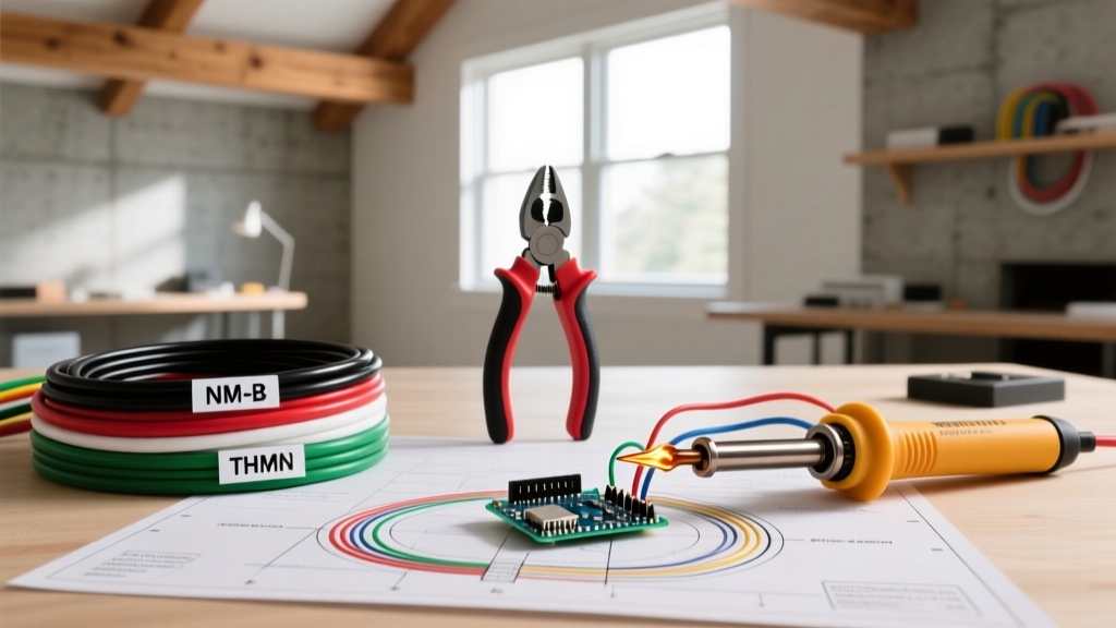
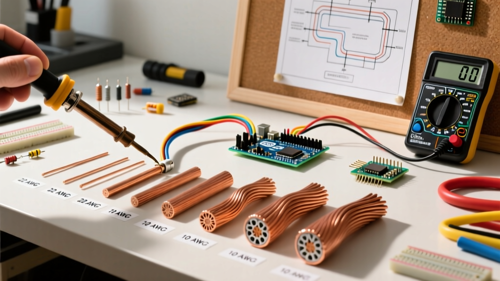
One of the most common causes of ballast failure and electrical fires is the misuse of wire types and improper stripping lengths. The primary branch circuit wiring (THHN/THWN) has different physical properties than the secondary ballast output wiring (AWM).
| Wire Type | Application | Voltage Rating | Temperature Rating | Required Strip Length |
|---|---|---|---|---|
| 14 AWG THHN (Solid/Stranded) | Branch Circuit to Ballast (Primary) | 600V | 90°C (194°F) | 5/8 inch (15.8 mm) |
| 18 AWG AWM 1015 (Stranded) | Ballast to Tombstone (Secondary) | 600V (Pulse rated higher) | 105°C (221°F) | 3/8 inch (9.5 mm) |
| 16 AWG TFN (Stranded) | Fixture Internal Wiring | 600V | 90°C (194°F) | 1/2 inch (12.7 mm) |
Critical Warning: Never use standard 90°C THHN wire for the secondary connections between an HID ballast and the socket. The high-voltage ignition pulses can degrade standard PVC THHN insulation over time, leading to micro-fractures and arc faults. Always use AWM (Appliance Wiring Material) or fixture wire specifically rated for high-frequency, high-pulse applications.
Step-by-Step Safe Installation Protocol
To mitigate shock and arc-flash hazards during electrical ballast wiring, follow this rigorous, OSHA-aligned installation sequence.
- Lockout/Tagout (LOTO): De-energize the circuit at the breaker panel. Apply a physical lock and tag. As outlined by OSHA's hazardous energy control standards, simply turning off a wall switch is insufficient and violates federal safety mandates for commercial maintenance.
- Verify Zero Energy: Use a CAT III 600V-rated True-RMS multimeter (such as the Fluke 117). Test the meter on a known live source, test the target ballast wires (Phase-to-Phase and Phase-to-Ground), and test the meter on the live source again (Live-Dead-Live method).
- Cap and Isolate: If working in a multi-ballast fixture where adjacent ballasts remain energized, physically cap all live wires with Wago 221-413 lever-nuts and secure them away from your work zone.
- Mount and Ground First: Secure the new ballast (e.g., a GE Multi-Voltage T8 electronic ballast) to the fixture chassis using the provided mounting studs. Immediately connect the green EGC pigtail to the chassis ground screw. Torque the screw to 12 in-lbs to ensure a gas-tight mechanical bond.
- Make Primary Connections: Connect the branch circuit Black (Hot) to the Ballast Black, and the branch circuit White (Neutral) to the Ballast White. Use purple or yellow wire nuts, ensuring no bare copper is exposed outside the skirt of the connector.
- Make Secondary Connections: Connect the blue and red ballast output wires to the lamp holders (tombstones). Ensure the 18 AWG stranded wire is twisted tightly before insertion into the lever-nut or crimp connector to prevent 'bird-caging' (strands splaying outward).
- Dress the Wires: Tuck all wiring neatly into the fixture channel. Ensure no wires are pinched between the ballast casing and the metal fixture housing, which could eventually cut through the insulation.
Troubleshooting and Edge-Case Failure Modes
Even with perfect installation, electrical ballast wiring can exhibit anomalous behaviors due to environmental factors or component degradation. Recognizing these edge cases prevents unnecessary part swapping and identifies hidden safety threats.
- The 'Ground Loop' Hum: If a newly wired magnetic or older electronic ballast emits a loud 60Hz hum, check for a ground loop. This occurs when the neutral and ground are bonded downstream of the main service disconnect, or when the ballast chassis is grounded to two different potentials. Use a millivolt meter to check for voltage potential between the fixture chassis and a verified building ground.
- Tombstone Arcing and Melted Sockets: If you find melted plastic on the lamp holders (tombstones), the issue is rarely the ballast itself. It is usually a poor bi-pin connection. When a fluorescent tube is not seated perfectly, the electrical resistance at the pin increases, generating intense localized heat. Always replace melted tombstones with UL-listed, push-in or rotary socket replacements rated for 600V.
- Thermal Runaway in Recessed Fixtures: When wiring ballasts in recessed troffers, ensure the ballast is not buried under blown-in insulation unless the fixture is explicitly rated as IC (Insulation Contact). A standard non-IC recessed fixture buried in insulation will trap the ballast's ambient heat (typically 40°C to 50°C above room temperature), causing the Class P protector to trip continuously or, in worst-case scenarios, igniting the surrounding cellulose insulation.
- End-of-Life (EOL) Lamp Effects: Modern electronic ballasts feature EOL detection circuitry. If a fluorescent tube develops a severe asymmetrical arc (one end glowing orange while the other remains dark), the ballast's microprocessor detects the abnormal voltage drop and will shut down entirely to prevent the socket from melting. If a technician replaces the ballast but leaves the aged lamp, the new ballast will immediately lock out. Always replace lamps in pairs when servicing a ballast.
Pro-Tip for Facility Managers: If you are managing a building with aging T12 magnetic ballasts, the cost of continuous electrical ballast wiring maintenance and replacement parts ($35–$60 per magnetic ballast) often exceeds the cost of a complete LED retrofit. According to EPA Energy Star lighting data, bypassing the ballast entirely and installing Type B (ballast-bypass) LED tubes eliminates the ballast failure point, reduces HVAC cooling loads by up to 15%, and removes the high-voltage ignition hazard from your facility's electrical infrastructure entirely.
Final Safety Directives
Electrical ballast wiring demands respect for high-voltage physics and strict adherence to the NEC. Never assume a circuit is dead based on a wall switch position, never substitute THHN for secondary pulse wiring, and never compromise on the equipment grounding conductor. By utilizing proper wire stripping tolerances, leveraging modern lever-nut connectors to prevent cold joints, and understanding the specific failure modes of gas-discharge lighting, electrical professionals can ensure safe, reliable, and code-compliant lighting systems for years to come.