
The Hidden Danger of Dynamic Loads in Ceiling Fan Electrical Wiring
When approaching ceiling fan electrical wiring, DIYers and even some general contractors often focus entirely on matching wire colors and ensuring the motor spins. However, the most critical safety factor is not the electrical connection itself, but the mechanical support of the junction box. Unlike static light fixtures, ceiling fans introduce continuous dynamic loads and low-frequency vibrations. Over months and years, these micro-vibrations can back out standard wire nuts, loosen mounting screws, and ultimately cause a catastrophic structural failure.
According to the U.S. Consumer Product Safety Commission (CPSC), improper mounting and degraded electrical connections are leading causes of ceiling fan-related property damage and injuries. In 2026, with the average premium smart ceiling fan weighing between 35 and 55 pounds, adhering to strict safety best practices and National Electrical Code (NEC) requirements is non-negotiable.
NEC Article 314.27(C): The Law on Junction Boxes
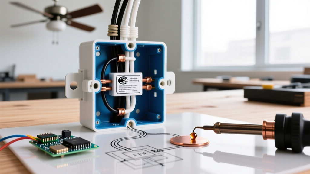
The National Electrical Code explicitly addresses the unique demands of ceiling fans under NEC Article 314.27(C). This section mandates that any outlet box used to support a ceiling fan must be specifically listed and marked by the manufacturer as suitable for that purpose.
Code Insight: A standard round or octagonal junction box rated for 35 lbs of static weight is legally and structurally insufficient for a ceiling fan, even if the fan weighs less than 35 lbs. The box must be explicitly marked 'Acceptable for Fan Support'.
Weight Thresholds and Box Selection
- Up to 35 lbs: Must use a UL-listed fan-rated junction box (e.g., Carlon CFSC218R, approx. $14). These boxes feature deeper threading and reinforced mounting ears to handle torque.
- 35 lbs to 70 lbs: Requires a heavy-duty fan-rated box that is directly secured to the building structure (joist) or supported by a listed structural brace system.
- Over 70 lbs: The fan must be supported independently of the junction box. The electrical box only serves to house the wire splices; the actual weight must be transferred to a structural beam via a dedicated mounting bracket.
Structural Bracing: Securing the Mount
If you are retrofitting a ceiling fan in an existing room where attic access is limited, you cannot simply screw a fan-rated box into the drywall or a distant joist. You must use an expandable hanger bar. The Westinghouse Saf-T-Brace (Model 0103000) remains the industry standard in 2026, costing around $18 at major hardware retailers. It expands between joists and locks into place with aggressive metal teeth that grip the wood, preventing rotation under dynamic load.
| Mounting Method | Max Weight Capacity | Vibration Resistance | Estimated 2026 Cost |
|---|---|---|---|
| Standard Octagonal Box | 35 lbs (Static Only) | Poor (Fails over time) | $3 - $5 |
| UL-Listed Fan-Rated Box | 70 lbs | Excellent | $10 - $18 |
| Retrofit Hanger Brace | 70 lbs | Superior | $18 - $25 |
| Direct Joist Mount (Lag Bolts) | 70+ lbs | Maximum | $5 - $10 (Hardware) |
Ceiling Fan Electrical Wiring: Conductors and Connections
Once the structural integrity is guaranteed, the focus shifts to the electrical splices. Ceiling fan motors draw significant inrush current when starting, which can generate localized heat at poorly made connections.
Wire Gauge and Circuit Sizing
Most residential ceiling fans operate on a standard 15-amp or 20-amp circuit. You will typically encounter 14 AWG (for 15A circuits) or 12 AWG (for 20A circuits) copper branch wiring. The fixture wire provided with the fan is often 16 AWG or 18 AWG stranded copper. Splicing solid branch wire to stranded fixture wire requires specific techniques to ensure the stranded wire does not wrap loosely around the solid wire, creating a high-resistance joint.
Modern Connector Best Practices
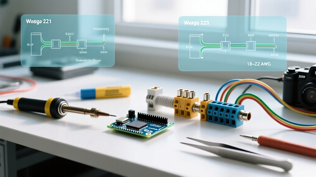
While traditional twist-on wire nuts (like the Ideal Yellow 73B) are code-compliant when installed correctly, the industry has largely shifted toward lever connectors for high-vibration environments. Wago 221 Series lever nuts (e.g., Wago 221-413 for 3 conductors, approx. $0.65 each) provide a gas-tight, vibration-proof connection. The lever mechanism applies consistent, spring-loaded pressure on both solid and stranded wires, eliminating the risk of a connection loosening due to the fan's rotational torque.
- Strip the wires: Use a precision stripper (like the Klein Tools 11057) to strip exactly 11mm (7/16 inch) of insulation. Do not nick the copper.
- Insert and clamp: Insert the solid branch wire and stranded fan wire into separate ports of the Wago 221 connector.
- Verify the ground: The bare copper or green insulated ground wire MUST be connected to the fan's grounding bracket and the junction box's green ground screw. Never leave a ground wire floating.
Critical Edge Cases and Failure Modes
Expert electrical work requires anticipating edge cases that standard guides ignore. Here are two high-risk scenarios frequently encountered in ceiling fan electrical wiring.
Edge Case 1: Aluminum Branch Wiring
Homes built between 1965 and 1973 often feature aluminum branch wiring. Aluminum is prone to galvanic corrosion when in direct contact with copper, and it exhibits 'cold creep,' meaning it deforms under pressure and loosens over time. Never use standard wire nuts to connect copper fan wires to aluminum branch wires. You must use a CU/AL rated connector, such as the AlumiConn 2-Port lug connector (approx. $4.50 each). These feature independent ports for each wire, coated with an antioxidant inhibitor (like Noalox) to prevent oxidation and thermal runaway.
Edge Case 2: Dimmer Switch Incompatibility
A common and dangerous mistake is wiring a ceiling fan to a standard incandescent/LED dimmer switch. Dimmers use TRIACs to chop the AC sine wave, which causes severe overheating in ceiling fan motors, resulting in a loud humming noise, degraded insulation, and eventual motor fire. If wall-based speed control is required, you must install a dedicated fan speed control switch, such as the Lutron Skylark SFSQ-F, which utilizes stepped impedance rather than phase-cutting to safely regulate motor speed.
Step-by-Step Safety Verification Protocol
Before energizing the circuit, run through this mandatory safety checklist to ensure compliance and operational safety:
- Lockout/Tagout: Turn off the breaker and secure the panel. Verify the absence of voltage using a non-contact voltage tester (e.g., Klein Tools NCVT-2) at the junction box.
- Pull Test: After making all wire splices, give each wire a firm, 3-pound pull test to ensure it is fully seated in the connector.
- Box Fill Calculation: Ensure the junction box has adequate volume. NEC Article 314.16 dictates box fill limits based on wire gauge. A standard 18 cubic inch fan-rated box is usually sufficient, but smart fans with bulky RF receivers may require a 21 cubic inch deep box.
- Clearance Check: Verify that the fan blades will maintain a minimum 7-foot clearance from the floor and an 18-inch clearance from any adjacent walls, as recommended by the EPA Energy Star guidelines for optimal airflow and safety.
Summary
Proper ceiling fan electrical wiring goes far beyond matching black to black and white to white. By respecting the dynamic loads involved, utilizing UL-listed fan-rated boxes, employing vibration-resistant connectors like Wago lever nuts, and avoiding catastrophic edge cases like dimmer incompatibility, you ensure a safe, code-compliant installation that will last for decades. For further reading on residential electrical fire prevention, consult the extensive reports provided by the National Fire Protection Association (NFPA).