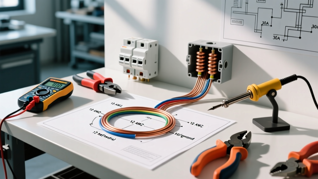

Decoding the Wiring Electric Water Heater Diagram
Reading a wiring electric water heater diagram is only the first step in a successful installation. While the schematic provided on the inside of the junction box cover shows you the logical flow of current from the upper thermostat to the lower thermostat and elements, it does not tell you what materials to procure or how to properly terminate the connections. In 2026, with the rise of smart hybrid water heaters and stricter local enforcement of the National Electrical Code (NEC), relying on outdated material lists or generic hand tools can lead to failed inspections, melted wire insulation, or catastrophic 'dry fire' element failures.
This guide bridges the gap between the theoretical diagram and the physical workbench, detailing the exact materials, wire gauges, and specialized tools required to execute the wiring safely and efficiently.
CRITICAL SAFETY NOTICE: According to NFPA 70 (National Electrical Code) Article 422.11(E), the branch-circuit rating for a storage water heater of 120 gallons or less must not be less than 125% of the nameplate load. Always verify your local jurisdiction's specific amendments before purchasing materials.
Essential Electrical Materials: Sizing by the Diagram
Most standard residential water heaters operate on 240V and feature dual 4500W elements. However, the diagram will vary based on the unit's total wattage. Procuring the correct wire and breaker is non-negotiable. Below is the definitive material matrix for standard 240V resistive water heaters.
| Heater Wattage (240V) | Amperage Draw | NEC 125% Rule Min Circuit | Wire Gauge (Copper) | 2-Pole Breaker Size |
|---|---|---|---|---|
| 3000W | 12.5A | 15.6A | 14 AWG (12 AWG Rec.) | 20A |
| 3800W | 15.8A | 19.7A | 12 AWG | 25A or 30A |
| 4500W | 18.75A | 23.4A | 10 AWG | 30A |
| 5500W | 22.9A | 28.6A | 10 AWG | 30A (Max for 10AWG) |
2026 Market Material Recommendations
- Cable: For standard 4500W units, purchase 10/2 NM-B (Romex) with ground. With copper prices stabilizing in early 2026, expect to pay approximately $0.85 to $1.10 per foot for quality Southwire or Cerrowire brands.
- Breaker: The Square D HOM230CP (Homeline 30A 2-Pole) or Eaton BR230 are the industry standards. They cost between $12 and $18 and feature clear trip indicators.
- Smart Heater Exception: If you are installing a smart heat pump unit (like the Rheem ProTerra), the wiring diagram will require a neutral wire for the control board. You must upgrade your material list to 10/3 NM-B to accommodate the L1, L2, Neutral, and Ground requirements outlined by the Department of Energy's heat pump water heater guidelines.
- Connectors: Use 3/4-inch NM cable connectors (e.g., Halex 3/4 in. Non-Metallic Twin-Screw) to secure the wire to the heater's junction box. Never run the cable through the knockout without a connector, as the sharp metal edge will slice the insulation over time due to thermal expansion and vibration.
The Right Tools: Beyond Basic Pliers
Executing the diagram flawlessly requires more than a standard screwdriver and lineman's pliers. Professional electricians use specialized tools to ensure termination integrity, which is the leading cause of water heater electrical fires.
| Task | Standard DIY Tool | Pro-Grade Tool (Recommended) | Why the Pro Tool Matters |
|---|---|---|---|
| Stripping 10 AWG | Utility Knife | Klein Tools 11055 Wire Stripper | Prevents nicking the copper conductor, which creates a hot spot and weakens the wire under load. |
| Terminal Torque | Standard Phillips Driver | Wera Torque Screwdriver (Set to 20 in-lbs) | Prevents 'thermal creep' where loose connections heat up, expand, and eventually melt the wire jacket. |
| Dressing Panel Wire | Lineman's Pliers | Knipex Flush Cutters | Allows for clean, flush cuts on zip ties and excess wire without leaving sharp, dangerous metal protrusions. |
Step-by-Step Diagram Execution & Termination
Once your materials are staged and your tools are ready, follow this sequence to translate the diagram into a physical, code-compliant connection.
- Prep the NM-B Cable: Strip back 8 inches of the outer yellow PVC jacket using a cable ripper (not a knife). Strip exactly 3/4 inch of insulation from the black, white (re-identified with black tape), and bare copper wires.
- Re-identify the Neutral: Standard 10/2 wire contains a white wire. Because 240V water heaters do not use a neutral (unless it is a smart unit), the white wire acts as your second hot leg (L2). The diagram will usually indicate this. Wrap the ends of the white wire with black electrical tape to signify it is a hot conductor, satisfying NEC 200.7(C)(2).
- Land the Ground First: Connect the bare copper ground wire to the green grounding screw inside the junction box, and pigtail it to the bare copper grounding wire coming from the unit's internal harness. A solid ground is critical for the diagram's safety loop.
- Terminate L1 and L2: Connect the black wire to L1 and the re-identified white wire to L2 using the supplied wire nuts (typically yellow or red 3M wire nuts for 10 AWG). Twist the wires clockwise and torque the wire nut until the wire twists slightly outside the nut.
- Verify Torque: If your unit features a screw-terminal block instead of wire nuts (common in commercial or tankless units), use your calibrated torque screwdriver. Most 10 AWG terminals require 20 to 25 inch-pounds of torque.
Common Diagram Misinterpretations & Failure Modes
Even experienced DIYers make critical errors when interpreting water heater schematics. Avoid these specific failure modes:
- The 'Dry Fire' Catastrophe: The diagram shows the upper thermostat controlling the lower thermostat. If you wire the elements directly to the power source, bypassing the thermostats, and turn on the power before the tank is 100% full of water, the elements will burn out in seconds. This is known as 'dry firing' and voids the warranty.
- Confusing 120V and 240V Diagrams: Many installation manuals include diagrams for both 120V point-of-use heaters and 240V whole-home heaters. Wiring a 120V element to a 240V circuit will cause the element to draw four times its rated wattage (P = V^2 / R), resulting in an immediate explosion of the element and a tripped breaker.
- Ignoring the High-Limit Reset: The diagram always routes power through the ECO (Energy Cut Off) high-limit switch on the upper thermostat. If you wire L1 directly to the element terminal, you bypass this critical safety device, creating a severe fire hazard if the primary thermostat contacts weld shut.
Frequently Asked Questions
Can I use 12/2 wire for a 4500W water heater?
No. A 4500W heater at 240V draws 18.75 Amps. Applying the NEC 125% continuous load rule (required for storage heaters under 120 gallons), the circuit must be rated for at least 23.4 Amps. 12 AWG wire is only rated for 20 Amps. You must use 10 AWG wire and a 30A breaker.
Does it matter if I swap L1 and L2 on the diagram?
For a standard resistive element water heater, alternating current (AC) means L1 and L2 are interchangeable. The elements will heat identically regardless of which hot leg is connected to which terminal. However, if you are wiring a smart water heater with a digital control board, strictly follow the manufacturer's L1/L2 designations, as the internal logic board may be polarity-sensitive or require a specific phase reference.
Why does my diagram show a 3-wire setup but my house has 4-wire?
Older diagrams often show a 3-wire setup (L1, L2, and a combined Neutral/Ground). Modern NEC codes strictly prohibit bonding the neutral and ground at the appliance. If your home's panel supplies a 4-wire circuit (L1, L2, Neutral, Ground) to the heater, simply cap the neutral wire with a wire nut and leave it unused in the junction box, connecting only the two hots and the dedicated ground to the unit. For more on appliance wiring safety, refer to the DOE Water Heater installation guidelines.