
Introduction to Trailer Brake Electrical Codes
When a 7,000-pound tandem-axle trailer is hurtling down the interstate at 65 mph, the wiring connecting its electric brakes to the tow vehicle is the only thing preventing a catastrophic jackknife. The wiring of electric trailer brakes is not merely a DIY hobbyist exercise; it is strictly governed by a matrix of automotive and federal safety standards. While the National Electrical Code (NEC / NFPA 70) governs the stationary electrical systems of your home and garage, mobile trailer systems fall under the jurisdiction of the Society of Automotive Engineers (SAE) and the Department of Transportation's Federal Motor Vehicle Safety Standards (FMVSS).
In this 2026 code explainer, we dissect the exact standards, wire gauges, circuit protection requirements, and failure modes associated with electric trailer brake wiring. Whether you are building a custom car hauler or rewiring a vintage Airstream, adhering to these specifications ensures legal compliance and, more importantly, functional safety.
Core Standards: SAE J286 and FMVSS 135
Before stripping a single wire, you must understand the regulatory framework. The two primary standards dictating trailer brake wiring are:
- SAE J286 (and SAE J1292): These standards dictate the physical layout, pinout, and color-coding for automotive trailer connectors (specifically the 7-way RV blade). They ensure interoperability between any tow vehicle and any trailer manufactured in North America.
- FMVSS 135 (Light Vehicle Brake Systems) & FMVSS 121 (Air Brake Systems): While primarily focused on hydraulic and air braking performance, the DOT's Federal Motor Vehicle Safety Standards (Title 49 CFR Part 571) mandate that trailers over a certain Gross Vehicle Weight Rating (GVWR) must possess an independent breakaway braking system. This directly dictates how the breakaway switch and battery must be wired into the brake circuit.
The 7-Way RV Blade: SAE Pinout and Wire Sizing Matrix
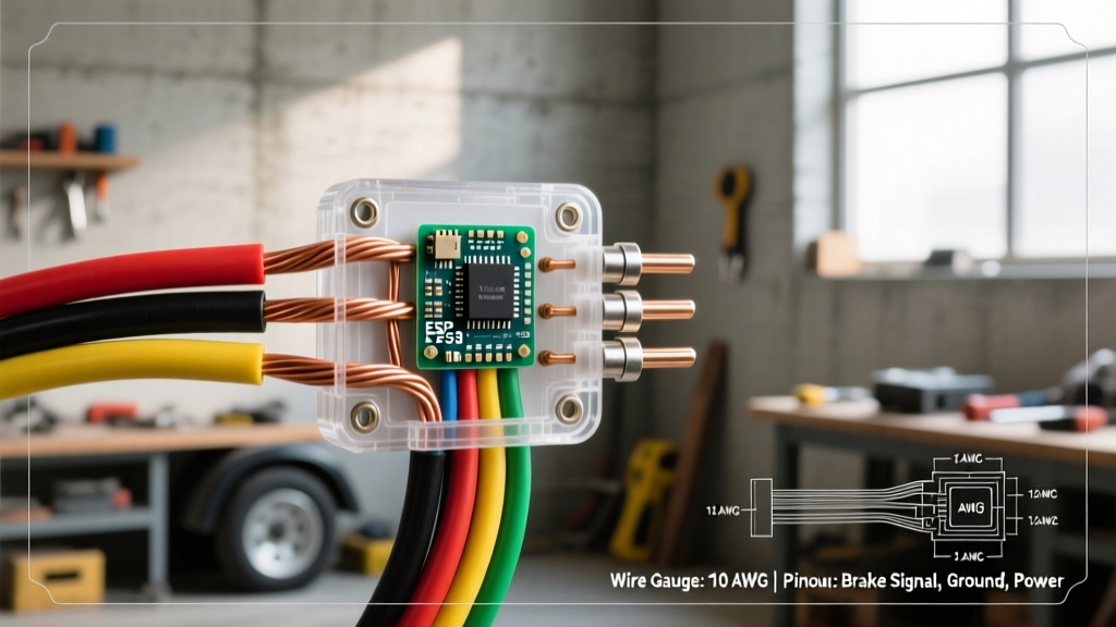
The 7-way RV blade is the undisputed standard for trailers equipped with electric brakes. While physical pin numbering can vary slightly between manufacturers like Hopkins and Curt, the SAE J286 color codes and functional assignments are absolute. Undersizing the wire for the brake circuit is a common code violation that leads to severe voltage drop, resulting in weak braking at the trailer axles.
| Function | SAE Standard Color | Minimum AWG (Code) | Recommended AWG (Best Practice) | Notes & Edge Cases |
|---|---|---|---|---|
| Electric Brakes | Blue | 12 AWG | 10 AWG | Use 10 AWG for runs exceeding 15 feet to mitigate voltage drop. |
| Ground (Chassis) | White | 10 AWG | 8 AWG | Must handle the return current for ALL trailer circuits simultaneously. |
| 12V Auxiliary / Breakaway Charge | Black | 12 AWG | 10 AWG | Requires inline diode to prevent backfeeding the tow vehicle. |
| Left Turn / Stop | Yellow | 16 AWG | 14 AWG | LED upgrades allow 16 AWG; incandescent requires 14 AWG. |
| Right Turn / Stop | Green | 16 AWG | 14 AWG | Same as left turn circuit. |
| Tail / Running Lights | Brown | 14 AWG | 12 AWG | Clearance lights draw cumulative current; size up for long trailers. |
| Reverse Lights | Purple | 16 AWG | 14 AWG | Often used to trigger reverse lockout solenoids on surge brake couplers. |
Wire Selection: Why PVC Fails and GXL Wins
A critical mistake in the wiring of electric trailer brakes is using standard PVC-jacketed wire (like THHN or cheap automotive primary wire) sourced from local hardware stores. Trailer wiring is subjected to extreme abrasion, UV exposure, and high ambient heat near the axles.
The Code-Compliant Choice: You must use SAE J1128 GXL or TXL wire.
- GXL (General Cross-Linked): Features a cross-linked polyethylene (XLPE) insulation rated for continuous operation at 125°C (257°F). It is highly resistant to road debris abrasion and chemical spills (oil, grease).
- TXL (Thin-Wall Cross-Linked): Offers the same 125°C rating but with a thinner insulation wall, saving weight and increasing flexibility in tight harness wraps.
In 2026, high-quality 10 AWG GXL wire costs approximately $0.85 to $1.10 per foot. Do not compromise on this material; PVC insulation will melt and short against the steel trailer frame when exposed to the radiant heat of heavy-duty brake magnets during prolonged mountain descents.
Breakaway Switch Wiring (FMVSS Compliance)
If a trailer detaches from the hitch, the breakaway switch must instantly apply full battery voltage to the trailer brake magnets. FMVSS regulations require this system to have its own dedicated power source, independent of the tow vehicle.
Step-by-Step Breakaway Integration
- The Power Source: Use a dedicated 12V Sealed Lead Acid (SLA) battery (minimum 12Ah) or a modern 12V 10Ah LiFePO4 drop-in replacement (retailing around $65-$85 in 2026). Mount it in a weatherproof enclosure (e.g., Tekonsha or Curt breakaway kits) on the trailer tongue.
- The Switch Mechanism: Wire the breakaway switch in series between the positive terminal of the breakaway battery and the blue brake output wire. The lanyard cable must be routed to the tow vehicle's frame, not the hitch ball.
- Isolation Diode: The tow vehicle must charge the breakaway battery via the 12V Aux (Black) wire. You must install a 1N5408 heavy-duty blocking diode or a dedicated solid-state battery isolation module on the charging line. Without this, when the breakaway pin is pulled, the trailer battery will backfeed voltage into the tow vehicle's ECU, potentially causing thousands of dollars in computer damage.
- Inline Fusing: Install a 20A ATO blade fuse within 6 inches of the breakaway battery's positive terminal to protect the switch wiring from dead-shorts.
Circuit Protection: Fuses vs. Auto-Reset Breakers
On the tow vehicle side, the blue brake output wire and the black 12V aux wire require overcurrent protection near the vehicle's battery. Never use standard blade fuses for the main trailer brake feed.
Electric brake magnets draw a massive inrush current when first engaged, and the resistance of the magnets drops as they heat up, increasing amperage draw. A standard 30A fuse will suffer from 'nuisance blowing' under heavy, repeated braking.
The Solution: Install a Type I (Auto-Resetting) or Type III (Push-Button Reset) 40A Circuit Breaker (such as the Bussmann / Eaton CB185 series, approx. $14).
Expert Rule of Thumb: The main circuit breaker must be mounted within 18 inches of the tow vehicle's positive battery terminal. This ensures the longest possible run of wire is protected against short-circuits in the event of a front-end collision or harness chafing.
The 'Phantom Ground' Phenomenon & Grounding Best Practices
The number one cause of erratic trailer brake behavior, dim running lights, and blown tow-vehicle fuses is a poor ground connection. Many DIYers rely on the 'phantom ground'—the electrical continuity provided by the steel hitch ball resting in the steel coupler. This is a severe code and safety violation.
As the trailer articulates over bumps, the hitch ball connection breaks and reconnects micro-seconds at a time, causing voltage spikes that can fry modern proportional brake controllers (like the Curt Spectrum or Tekonsha Prodigy P3).
How to Execute a Code-Compliant Ground
- Dedicated White Wire: Run a dedicated 8 AWG or 10 AWG white ground wire from the 7-way plug directly to the trailer frame.
- Surface Prep: Use a wire wheel or sandpaper to remove all paint, powder coating, and rust down to bare, shiny steel at the grounding point.
- Hardware: Use a stainless steel bolt, a flat washer, and a star lock washer. The star washer bites into the bare metal, ensuring a vibration-proof, gas-tight electrical connection.
- Corrosion Protection: Apply a dab of dielectric grease over the completed connection. Never put dielectric grease between the ring terminal and the bare metal; it is an insulator and will block the current.
- Terminal Crimping: Use adhesive-lined, heat-shrink ring terminals (e.g., 3M Highland or Glarks marine grade). Crimp with a ratcheting tool (like the Titan 11477) to ensure a cold-weld mechanical bond. When heated, the adhesive melts and seals out moisture, preventing the green corrosion that plagues standard vinyl-insulated terminals.
Frequently Asked Questions: Code & Standards
Do I need a brake controller if my trailer has electric-over-hydraulic (EOH) brakes?
Yes. EOH actuators (like the HydraStar or Dexter DX series) still require a 12V PWM (Pulse Width Modulation) signal from an electronic brake controller in the cab. However, you must ensure your brake controller is explicitly configured for EOH mode. Sending standard electric-magnet voltage curves to an EOH actuator will result in delayed, jerky braking and premature pump failure.
Can I use a 4-way flat connector and adapt it to a 7-way for brakes?
No. A 4-way flat connector lacks the dedicated blue (brake) and black (12V aux) circuits. Using adapters that attempt to 'pull' brake current from the tail light or turn signal circuits is a direct violation of SAE J286 and will result in total electrical system failure when the brakes are applied.
What is the acceptable voltage drop for the brake circuit?
According to SAE International best practices, voltage drop on a 12V DC trailer circuit should not exceed 3% under continuous load. For a 12V system, this means a maximum drop of 0.36V. If you measure 12.6V at the brake controller output and only 10.5V at the trailer axle magnets, your wire gauge is too small, your ground is compromised, or your connector pins are corroded.
By adhering strictly to SAE J286 pinouts, utilizing GXL cross-linked wiring, and implementing proper circuit protection and grounding protocols, your trailer's braking system will remain reliable, legally compliant, and safe for the long haul.