
The Critical Intersection of Diagrams and Electrical Code
Interpreting a diagram for wiring is not merely an exercise in tracing lines; it is a rigorous translation of engineering intent into physical, code-compliant reality. Whether you are roughing in a new commercial facility or troubleshooting a complex residential subpanel, the diagram serves as the legal and technical blueprint. Misreading a single symbol or ignoring a line type can lead to catastrophic arc flash events, equipment failure, or severe violations of the National Electrical Code (NEC). According to the National Fire Protection Association (NFPA), improper wiring methods and misapplied overcurrent protection remain leading causes of electrical fires in commercial structures.
This guide decodes the standard anatomy of wiring diagrams through the lens of the 2023/2026 NEC cycle, providing electricians and engineers with the actionable frameworks needed to verify that paper schematics align with physical code requirements.
The Three Tiers of Electrical Diagrams
Before applying code rules, you must identify which type of diagram you are holding. The industry relies on three distinct formats, each serving a different phase of installation and troubleshooting:
- Single-Line Diagrams (SLDs): Used primarily in commercial and industrial settings to show the power distribution path from the utility transformer down to branch circuits. SLDs are critical for calculating available fault current and establishing NFPA 70E arc flash boundaries.
- Ladder Diagrams: Standard in motor control and automation. They separate the power circuit (usually on the left) from the control circuit (on the right), making it easy to trace logic sequences without getting tangled in physical wire routing.
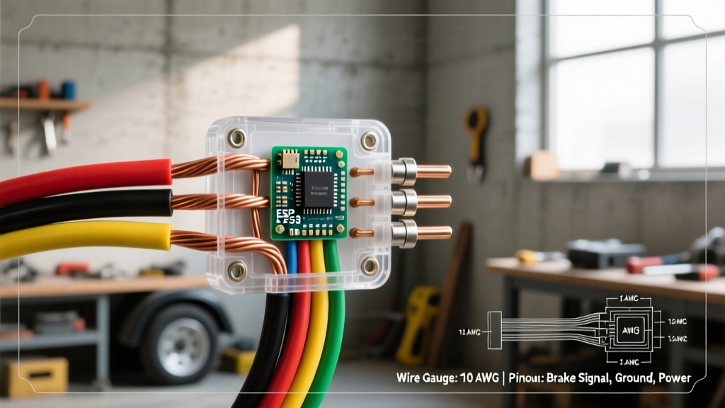
- Physical Wiring Diagrams: The most literal representation, showing exact terminal connections, wire colors, and physical routing. These are indispensable for panel builders and final terminations.
Translating Diagram Symbols to NEC Articles
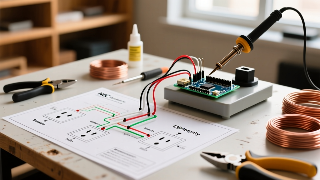
A professional diagram for wiring will embed NEC requirements directly into its symbology. Here is how to map common diagram elements to specific code articles.
Conductor Sizing and Ampacity (NEC Article 310)
Diagrams typically denote wire gauge next to the conductor line (e.g., 3/C #12 AWG THHN). Under NEC Article 310.14, you must verify the insulation type against the environment. If the diagram specifies THHN (90°C rating) but the wire is routed through a wet location or a boiler room, you must downgrade to the 75°C or 60°C ampacity column per NEC Table 310.16, or substitute XHHW-2 wire. Never blindly follow the gauge on the diagram without verifying the ambient temperature correction factors in NEC Table 310.15(B)(1).
Overcurrent Protection Devices (NEC Article 240)
Breaker and fuse symbols on a diagram must be cross-referenced with the conductor ampacity. A common edge case occurs with motor circuits. NEC Article 430.52 allows motor branch-circuit short-circuit and ground-fault protection to be sized significantly higher than the motor's full-load current (up to 250% for inverse-time breakers) to accommodate starting inrush. However, the overload protection (often shown as a separate thermal element symbol on the diagram) must be sized strictly between 115% and 125% of the motor nameplate FLC.
Equipment Grounding Conductors (NEC Article 250)
Grounding symbols (the classic three descending horizontal lines) dictate the Equipment Grounding Conductor (EGC). If a diagram shows a 400A feeder protected by a 400A breaker, NEC Table 250.122 mandates a minimum 3 AWG copper or 1 AWG aluminum EGC. If the ungrounded conductors are upsized for voltage drop, NEC 250.122(B) requires the EGC to be upsized proportionally—a detail frequently omitted on basic schematics but strictly enforced by inspectors.
Matrix: Line Types and Code Implications
The style of the line drawn on a diagram for wiring carries specific meaning regarding physical installation and code compliance.
| Line Style | Typical Meaning | NEC / Installation Implication |
|---|---|---|
| Solid Line | Physical electrical connection / Power circuit | Must follow NEC Article 300 wiring methods; requires physical separation from low-voltage lines. |
| Dashed Line | Mechanical linkage or concealed wiring | If concealed, must comply with NEC 334.40 for NM cable or Article 358 for EMT routing behind walls. |
| Dotted Line | Control / Logic / Future connection | Often Class 1 or Class 2 circuits (NEC Article 725); requires specific derating if run in the same raceway as power. |
| Wavy Line | Flexible cord or cable | Must comply with NEC Article 400; cannot be used as a substitute for fixed wiring methods (NEC 400.8). |
Edge Cases: MWBCs and AFCI/GFCI Mapping
Modern diagrams must account for the expanded AFCI and GFCI requirements in the latest NEC cycles. When reviewing a residential or light-commercial diagram, look for specific breaker symbols denoting combination-type AFCI or dual-function (AFCI/GFCI) protection.
Multi-Wire Branch Circuits (MWBC)
If a diagram shows two hot conductors (typically Black and Red) sharing a single neutral (White), you are looking at an MWBC. Under NEC 210.4(B), the diagram must indicate a simultaneous disconnect mechanism. This is usually represented by a tie-bar symbol linking two single-pole breakers, or a single double-pole breaker symbol. If the diagram shows two independent single-pole breakers on different phases without a handle tie, it is a direct code violation that risks overloading the shared neutral and presents a lethal shock hazard during maintenance.
Expert Insight: Never assume a neutral bus bar is safe to work on just because the main breaker is off. In commercial facilities with multiple service disconnects, always verify the single-line diagram to ensure no backfed generators or solar PV systems (NEC Article 705) are energizing the bus from an alternate source.
Pre-Energization Verification Protocol
Once the physical installation matches the diagram for wiring, follow this 5-step verification protocol before throwing the main disconnect:
- Torque Verification: Use a calibrated torque screwdriver to verify all terminations. Standard 15A and 20A receptacles typically require 40 in-lbs, while larger lug terminations must match the manufacturer's spec sheet to comply with NEC 110.14(D).
- Insulation Resistance Testing: Use a megohmmeter (e.g., Fluke 1587) to test phase-to-ground and phase-to-phase insulation. Readings below 1 megohm indicate compromised wire insulation or moisture ingress.
- Continuity and Grounding Path: Verify the equipment grounding conductor path from the furthest outlet back to the main bonding jumper using a low-resistance ohmmeter.
- Voltage Drop Calculation: Measure the actual circuit length and calculate voltage drop. While the NEC recommends a maximum 3% drop for branch circuits (Informational Note to 210.19), many sensitive commercial electronics require stricter 1.5% thresholds.
- Polarity and Phasing Check: Ensure all single-phase receptacles have correct hot/neutral polarity, and verify L1-L2-L3 phase rotation on three-phase motors using a phase rotation meter to prevent reverse operation.
Final Thoughts on Diagram Literacy
A diagram for wiring is a living document that bridges the gap between design and physical execution. By rigorously cross-referencing schematic symbols with the latest NEC articles, electricians can preemptively catch design flaws, ensure long-term system reliability, and guarantee the safety of the building's occupants. Always consult the Occupational Safety and Health Administration (OSHA) guidelines for electrical safety practices, and refer to NEMA standards when verifying specific equipment enclosure and component ratings.