
Understanding the 3-Way Switch Circuit Architecture
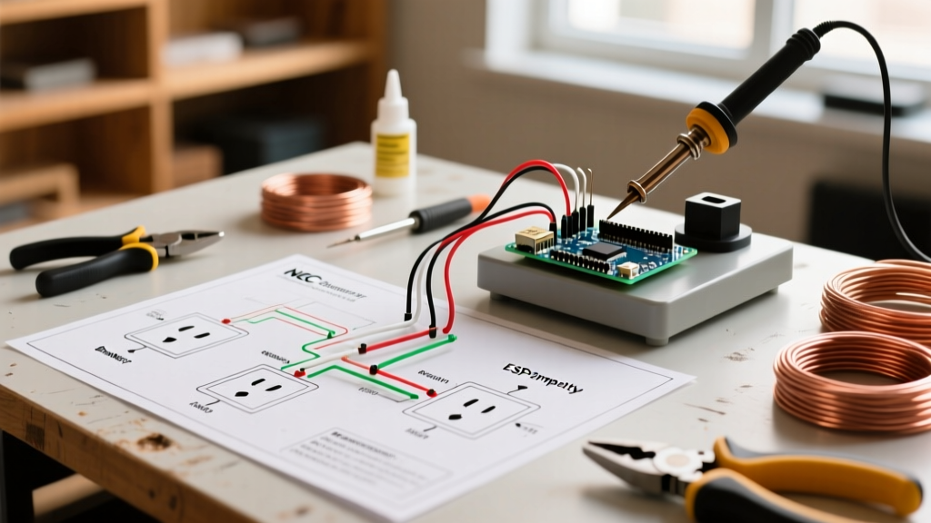
When homeowners and DIYers search for electrical wiring two switches one light, they are technically looking to install or repair a 3-way switch circuit. This configuration allows a single lighting load to be controlled from two distinct locations, such as the top and bottom of a staircase or opposite ends of a hallway. While the concept is straightforward, the execution involves complex traveler wires, shared neutrals, and strict adherence to the National Electrical Code (NEC). Improper wiring in these circuits is a leading cause of arc faults, stray voltage, and electrical fires.
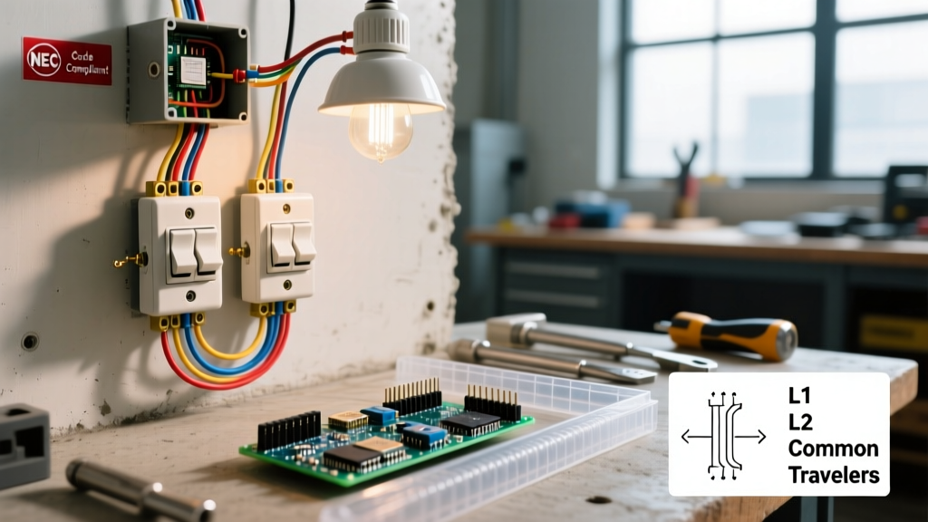
Unlike a standard single-pole switch that simply breaks the hot leg, a 3-way setup relies on a pair of brass-colored traveler terminals and a single dark-colored common terminal. Misidentifying the line (power source), load (light fixture), and travelers will result in a circuit that either fails to operate, creates a dead short, or leaves the switch chassis energized—a severe shock hazard.
2026 NEC Safety Mandates for Switch Loops
The NEC has evolved significantly to address modern electrical loads and smart home integrations. If you are pulling new cable or remodeling an existing 3-way circuit in 2026, you must comply with updated safety mandates.
The Grounded Conductor (Neutral) Requirement
Under NEC Article 404.2(C), switch boxes controlling lighting loads must now include a grounded circuit conductor (neutral wire). Historically, electricians used a 2-wire cable (14/2 or 12/2) to create a 'switch loop,' sending hot down to the switch and returning a switched hot on the white wire. This is now a code violation in new construction and major remodels.
- Safety Rationale: Smart switches, timers, and motion sensors require a continuous 120V standby power source. Without a neutral, these devices leak current through the light bulb (causing LED ghosting) or rely on the equipment grounding conductor, which is a severe shock and fire hazard.
- Execution: Always run 14/3 or 12/3 NM-B (Romex) cable between the switch boxes and the ceiling canopy to ensure a dedicated neutral and separate travelers are available at every junction point.
Lockout/Tagout (LOTO) and Verification Protocol
Before touching a single wire nut, you must establish a zero-energy state. The OSHA Lockout/Tagout standard is not just for industrial facilities; it is a critical life-saving protocol for residential electrical work.
- Identify and Isolate: Locate the correct breaker in the main service panel. Turn it to the OFF position and apply a physical lock or heavy-duty tape with a warning tag.
- Primary Test (NCVT): Use a Non-Contact Voltage Tester (NCVT), such as the Klein Tools NCVT-2, to scan the exterior of the switch plates and the wires inside the box.
- Secondary Test (Multimeter): NCVTs can yield false negatives due to shielded cables or low voltage. Use a True RMS multimeter (e.g., Fluke 117) set to AC Voltage. Test from the suspected hot wire to the bare ground, and then to the neutral. A reading of 0.0V confirms a safe working environment.
Step-by-Step Safe Wiring Execution
Follow this precise sequence to ensure mechanical integrity and electrical safety when wiring your two switches and one light.
Step 1: Grounding and Pigtailing
Never daisy-chain ground wires through the switch yoke. Use a green wire nut or an Ideal Twist-On connector to pigtail all bare copper ground wires in the box, including a dedicated 6-inch pigtail that terminates under the green grounding screw on the switch. This ensures that if the switch is removed for maintenance, the downstream ground path remains intact.
Step 2: Identifying Line, Load, and Travelers
Use a process of elimination and your multimeter (with power temporarily restored and extreme caution) to tag your wires. The Line wire brings constant 120V from the panel. The Load wire carries switched power to the fixture. The two Travelers run between the two 3-way switches. Tag the travelers with blue electrical tape to prevent future confusion.
Step 3: Torque Specifications
According to NEC 110.14(D), electrical connections must be torqued to the manufacturer's specifications. Loose terminal screws cause micro-arcing, which generates immense heat and melts the switch housing. Use a calibrated torque screwdriver, like the Wiha 61100, set to the switch manufacturer's spec (typically 14 to 16 inch-pounds for standard 15A Leviton or Lutron switches).
Failure Mode and Troubleshooting Matrix
When an existing electrical wiring two switches one light setup fails, avoid randomly swapping wires. Use this diagnostic matrix to identify the root cause safely.
| Symptom | Probable Cause | Safe Corrective Action |
|---|---|---|
| Light only turns on/off from Switch A, but Switch B does nothing. | Traveler wire disconnected or broken at Switch B; common terminal miswired. | Verify continuity on traveler wires with a multimeter. Ensure the common (dark) screw is not mistakenly holding a traveler. |
| Light works, but switch faceplate is warm to the touch. | Loose terminal screw causing high-resistance micro-arcing; overloaded circuit. | Cut power. Torque all terminal screws to 14 in-lbs. Check if dimmer is rated for the total LED wattage. |
| Breaker trips immediately when either switch is toggled. | Dead short; ground wire touching a hot traveler or common terminal. | Inspect wire insulation for nicking. Ensure no bare copper is exposed outside the wire nut or terminal clamp. |
| LED bulbs flicker or glow faintly when OFF. | Smart switch leaking current through ground; missing neutral wire at switch. | Install a neutral wire per NEC 404.2(C) or install an Lutron LUT-MLC capacitor at the light fixture. |
Recommended Components for Arc Fault Prevention
The quality of your hardware directly impacts the safety of a 3-way circuit. Cheap, builder-grade switches often feature inferior internal contacts that degrade rapidly under the inductive load of modern LED drivers.
- Standard 3-Way Switch: Leviton Decora 5603-2W (15A, 120V). Features heavy-duty steel straps and deep-cleat terminal screws that prevent wire slip-out.
- Smart/Dimmer 3-Way: Lutron Maestro MACL-153MH. Requires a neutral wire and utilizes advanced phase-cut dimming that prevents LED flickering and overheating.
- Circuit Protection: Eaton BR215AFC (15A Arc Fault Circuit Interrupter). The Consumer Product Safety Commission strongly recommends AFCI protection for all bedroom, living room, and hallway lighting circuits to detect and extinguish dangerous parallel and series arcs before they ignite surrounding wood framing.
Expert Safety Warning: Never use the 'backstab' or push-in wire holes on the back of a 3-way switch. These spring-loaded connections are notorious for losing tension over time, especially when subjected to the thermal expansion and contraction cycles of high-wattage lighting loads. Always use the side terminal screws and wrap the wire clockwise around the screw so that tightening the screw pulls the wire loop tighter, rather than pushing it out.
Final Inspection and Energization
Once all connections are made, torqued, and grounded, carefully fold the wires into the back of the electrical box. Use a 'Z-fold' technique: push the ground wires to the very back, fold the neutrals into the middle, and place the hot/traveler wires at the front. This prevents pinching the insulation against the metal box edges when you drive the mounting screws. Restore power at the panel and test the circuit from both locations. If the light operates correctly from both switches without any buzzing, flickering, or heat generation, your 3-way installation is safe, code-compliant, and built to last.