
The Evolution of Home Project Displays
When building custom smart home interfaces—such as wall-mounted thermostats, indoor air quality monitors, or automated irrigation controllers—the display is your primary user touchpoint. While OLEDs and TFTs have grown in popularity, the classic 16x2 character LCD remains a staple for DIY electrical projects due to its extreme reliability, low power consumption, and high visibility in direct sunlight. However, mastering lcd display arduino wiring requires navigating two distinct paradigms: the legacy parallel HD44780 standard and the modern I2C backpack method. This guide provides a comprehensive, electrician-grade breakdown of both wiring topologies, tailored for permanent home installations.
Component Selection and Project BOM
Before pulling wire through your walls or breadboarding a prototype, you must select the correct display and microcontroller combination. For home automation, the Arduino Uno R4 Minima or the classic Nano Every are preferred for their 5V logic levels, which natively match standard LCD requirements without needing logic level shifters.
| Component | Model / Specification | Est. Price (2026) | Best Use Case |
|---|---|---|---|
| Microcontroller | Arduino Uno R4 Minima | $28.00 | Central hub for multi-sensor home projects |
| I2C LCD Module | HiLetgo 16x2 with PCF8574 Backpack | $9.50 | Wall-mounted displays requiring minimal wiring |
| Parallel LCD | Elegoo 1602A HD44780 (Bare) | $6.00 | Custom PCB integration where I2C overhead is unwanted |
| Wiring | 22 AWG Solid Core (Prototyping) / 24 AWG Stranded (In-Wall) | $15.00 / spool | Breadboarding vs. permanent termination |
| Potentiometer | 10kΩ Linear Taper (B10K) | $0.50 | Contrast tuning for bare parallel LCDs |
Method 1: I2C Backpack Wiring (The 4-Wire Standard)
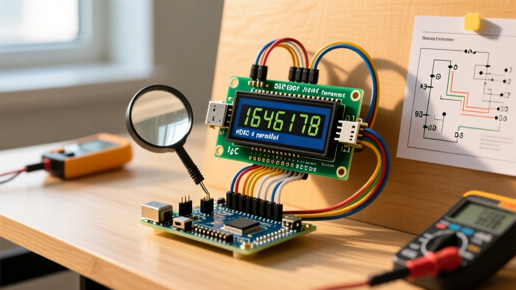
For 90% of home DIY projects, using an I2C (Inter-Integrated Circuit) backpack is the superior choice. It reduces the wiring complexity from 16 pins down to just 4, freeing up critical GPIO pins on your Arduino for relays, sensors, and communication modules.
Pin Mapping and Physical Connections
The I2C protocol relies on a synchronous serial bus. When wiring your I2C LCD to an Arduino Uno R3 or R4, follow this exact pinout:
- GND: Connect to Arduino GND. Ensure this shares a common ground with your power supply.
- VCC: Connect to Arduino 5V. Warning: Do not connect to 3.3V, as the HD44780 controller and the backlight LED require 4.5V to 5.5V for proper operation and illumination.
- SDA (Serial Data): Connect to Arduino A4 (on Uno R3) or the dedicated SDA pin near the AREF pin (on Uno R4/Nano).
- SCL (Serial Clock): Connect to Arduino A5 (on Uno R3) or the dedicated SCL pin.
The PCF8574 vs. PCF8574A Address Trap
One of the most common failure modes in lcd display arduino wiring involves I2C address conflicts. The I2C backpacks are built on either the PCF8574 or PCF8574A I/O expander chip. While they look identical, their base I2C addresses differ:
Expert Insight: PCF8574 backpacks typically default to
0x27. PCF8574A backpacks default to0x3F. If your code compiles but the screen remains blank, you are likely using the wrong address in your initialization string. Always run an I2C Scanner sketch before hardcoding addresses into your home automation firmware.
To avoid the legacy headaches of the LiquidCrystal_I2C library, which requires manual pin mapping for different backpack manufacturers, we strongly recommend installing the hd44780 library by Bill Perry via the Arduino Library Manager. It features an hd44780_I2Cexp class that automatically detects the I2C address and the internal pin mapping of the backpack, eliminating hours of troubleshooting.
Method 2: Parallel HD44780 Wiring (The 16-Pin Classic)
When designing a custom printed circuit board (PCB) for a permanent home installation, or when you have exhausted your I2C bus capacity, wiring a bare 16-pin parallel LCD is necessary. This method operates in 4-bit mode, requiring 6 data/control wires plus power and contrast circuitry.
| LCD Pin | Symbol | Arduino Connection | Function |
|---|---|---|---|
| 1 | VSS | GND | Logic Ground |
| 2 | VDD | 5V | Logic Power Supply |
| 3 | V0 | Wiper of 10kΩ Pot | Contrast Adjustment (Target ~0.5V) |
| 4 | RS | Digital Pin 12 | Register Select (Command vs. Data) |
| 5 | RW | GND | Read/Write (Hardwired to Write mode) |
| 6 | E | Digital Pin 11 | Enable Strobe |
| 7-10 | D0-D3 | Not Connected | Unused in 4-bit mode |
| 11-14 | D4-D7 | Pins 5, 4, 3, 2 | Bi-directional Data Bus |
| 15 | A | 5V (via 100Ω Resistor) | Backlight Anode |
| 16 | K | GND | Backlight Cathode |
Pro-Tip for Contrast (Pin 3): In modern high-contrast LCD modules, you can often bypass the bulky 10kΩ potentiometer entirely. Simply connect a fixed 1kΩ resistor between V0 (Pin 3) and GND. This provides the optimal ~0.4V to 0.6V drop required for crisp text rendering, saving space inside your wall-mounted enclosure.
Advanced Home Installation: Long Runs and Cat5e
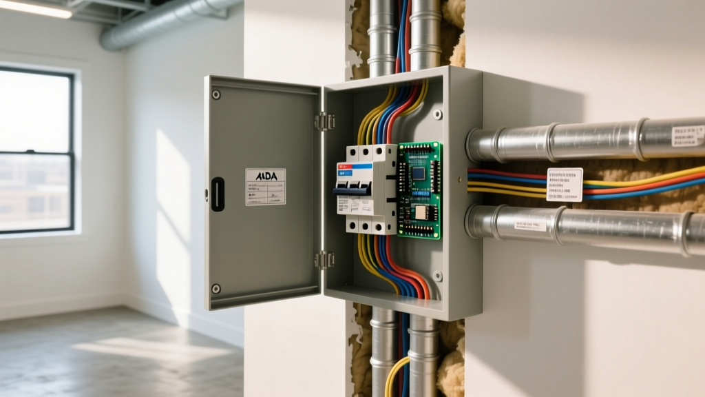
In residential smart home projects, you rarely place the Arduino right next to the display. You might mount the LCD in a living room wall plate while the Arduino and relay bank sit in a basement utility closet. Running standard jumper wires over 10 feet will result in severe signal degradation and voltage drop.
The Cat5e I2C Wiring Hack
Standard Ethernet cable (Cat5e) is exceptional for low-voltage DIY wiring due to its twisted pairs, which provide natural electromagnetic interference (EMI) rejection. When routing I2C to an LCD over distances up to 5 meters:
- Use one twisted pair for SDA and GND.
- Use a second twisted pair for SCL and GND.
- Use the remaining wires, bundled in parallel, for 5V VCC to minimize voltage drop.
Managing I2C Bus Capacitance
The I2C specification limits bus capacitance to 400pF. Long cables act as giant capacitors, rounding off the sharp square waves of your digital signals and causing the LCD to display garbage characters or lock up. According to the Arduino Wire Library Documentation, the internal pull-up resistors on the microcontroller are often too weak (typically 20kΩ - 50kΩ) for long runs. Solution: Solder external 4.7kΩ pull-up resistors between the SDA/SCL lines and the 5V VCC line directly at the LCD backpack. This stiffens the signal edges and restores reliable communication.
Troubleshooting Matrix: Fixing Blank Screens and Garbage Text
Even with perfect wiring, environmental factors and library mismatches can cause failures. Use this diagnostic matrix to resolve common home project issues:
- Symptom: Screen is completely blank, backlight is ON.
Diagnosis: Contrast voltage (V0) is incorrect, or initialization failed. Fix: Adjust the potentiometer. If using I2C, verify the address using the Adafruit I2C Scanner tool. - Symptom: Backlight is OFF, screen shows faint blocks.
Diagnosis: Backlight pins (A/K) are unpowered or reversed. Fix: Check Pin 15 and 16. Ensure you are using 5V, not 3.3V. - Symptom: Display shows a single row of solid white/black blocks.
Diagnosis: The LCD controller has not been initialized by the Arduino. Fix: Check the RS and E pins (parallel) or verify I2C clock speed. Reduce I2C speed to 50kHz in the Wire library if using long cables. - Symptom: Garbage characters or shifting text.
Diagnosis: Noise on the data bus or inadequate grounding. Fix: Ensure the Arduino GND and the LCD GND share a direct, thick wire. Add a 100µF decoupling capacitor across the VCC and GND pins at the LCD to suppress voltage spikes caused by the backlight LED.
Summary
Successful lcd display arduino wiring hinges on choosing the right interface for your physical constraints. Use I2C with the hd44780 library for rapid, reliable wall-mounted deployments, and reserve parallel wiring for custom PCB integrations. By respecting I2C capacitance limits on long cable runs and properly managing contrast voltages, your home automation interfaces will remain legible and robust for years to come.