
The Critical Role of Compliance in Aftermarket Car Audio
As vehicle electrical architectures evolve in 2026, integrating aftermarket electronics requires more than just matching wire colors. Modern vehicles utilize high-speed CAN-FD networks, automotive Ethernet, and sensitive multiplexed data buses. When referencing a wiring harness diagram for JVC car stereo units—such as the popular KW-M560BT multimedia receiver or the KD-X270BT mechless deck—installers and inspectors must adhere to strict automotive electrical standards. A poorly executed harness integration can lead to parasitic battery drains, alternator whine, or catastrophic ECU (Engine Control Unit) failures.
This inspection and compliance guide provides a rigorous framework for verifying aftermarket JVC head unit installations. By aligning with the Consumer Technology Association (CTA) and IPC/WHMA-A-620 harness standards, electrical inspectors and advanced DIYers can ensure safety, reliability, and warranty compliance.
Decoding the Wiring Harness Diagram for JVC Car Stereo Models
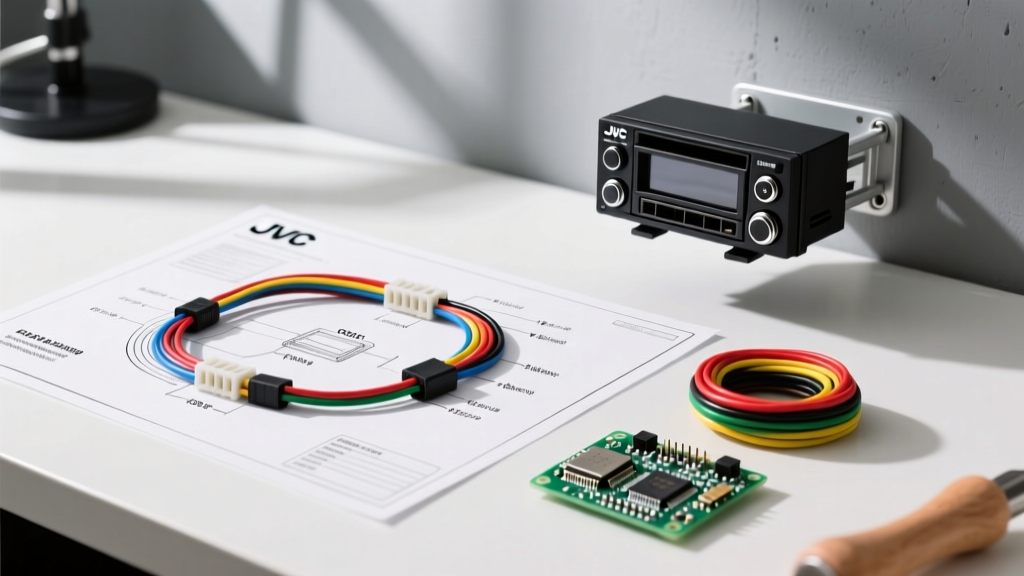
JVC adheres to the CEA (Consumer Electronics Association) color-coding standard for its aftermarket harnesses. However, inspecting an installation requires verifying that the vehicle-side adapter (e.g., a Metra 70-1761 or an Axxess AX-TOY6SWC-32V) correctly maps to the JVC pigtail. Below is the standard compliance matrix for JVC 16-pin and 22-pin harness configurations.
| Wire Color | Function | Inspection Criteria & Compliance Notes |
|---|---|---|
| Yellow | Constant 12V (Memory) | Must be fused within 7 inches of the battery or power source. Verify voltage is 12.2V-12.6V with ignition off. |
| Red | Switched 12V (Accessory) | Should read 0V when the vehicle is off. Must not be spliced into a CAN-bus wake-up wire. |
| Black | Chassis Ground | Must be 16 AWG or thicker. Must terminate to a bare metal chassis point, not a plastic dash support or factory wire. |
| Blue / White | Amplifier Turn-On | Verify it outputs 12V only when the JVC unit is powered on. Prevents battery drain from external amps. |
| Orange / White | Illumination / Dimmer | Must be connected to a variable dimmer circuit, not a 12V headlight feed, to prevent JVC display burnout. |
| Purple / Green / Gray / White | Speaker Outputs (Front/Rear) | Verify phase (positive/negative) with a pop-tester. Ensure no speaker wire is grounded to the chassis. |
CTA & IPC Standards: The Benchmark for Harness Inspections
Professional automotive electrical inspections rely on two primary frameworks to evaluate harness quality:
- CTA-2006 (Mobile Audio Standards): Dictates power wire gauge, fusing requirements, and signal-to-noise ratio baselines. According to the Consumer Technology Association, proper wire gauge selection is critical to prevent voltage drops that can cause JVC head units to reboot during heavy bass transients.
- IPC/WHMA-A-620: The industry standard for cable and wire harness assemblies. As outlined by the IPC requirements, this standard defines acceptable crimp profiles, solder wetting, and heat-shrink encapsulation. An inspector will reject any harness splice that exhibits 'cold crimps' or exposed copper strands.
Inspector's Note: In 2026, many insurance providers and dealership service centers will void electrical warranties if aftermarket harnesses are spliced using 'Scotch-Lok' or T-tap connectors. These devices sever copper strands and introduce moisture ingress points, violating basic SAE J1128 low-voltage primary cable integrity standards.
Step-by-Step Inspection Protocol for JVC Harnesses
When auditing a newly installed JVC car stereo, follow this systematic inspection flow to ensure the wiring harness diagram was executed flawlessly.
1. Visual and Mechanical Termination Audit
Inspect the physical connections between the JVC harness and the vehicle adapter.
- Solder & Heat Shrink: The gold standard. Look for adhesive-lined marine-grade heat shrink (e.g., 3M 562) that has sealed completely, forming a waterproof barrier. This is crucial behind the dash where A/C evaporator condensation can cause shorts.
- Posi-Twist / Posi-Tap: Acceptable for low-current signal wires (like steering wheel control data lines). Ensure the internal brass cutting blade has fully penetrated the wire insulation without severing the copper core.
- Crimp Caps: Must be compressed using a ratcheting crimper. A manual pull-test (applying roughly 5-10 lbs of force) should not dislodge the wire from the crimp barrel.
2. Voltage Drop Testing on the Ground Circuit
A common failure mode in JVC installations is the 'ground loop,' which manifests as a high-pitched alternator whine through the speakers. This occurs when the ground wire shares a return path with high-current vehicle accessories.
- Set a digital multimeter to DC Volts.
- Place the red probe on the JVC harness's black ground wire (as close to the head unit as possible).
- Place the black probe directly on the vehicle's bare metal chassis or negative battery terminal.
- Turn the JVC unit on and play a test tone at 50% volume.
- Compliance Threshold: The voltage drop must read less than 0.1V DC. If it reads higher, the ground point is corroded, undersized, or shared with a noisy factory module.
3. Parasitic Draw Verification
Modern JVC stereos feature quick-boot capabilities that draw a small amount of current from the constant 12V (Yellow) wire. However, a miswired harness can cause excessive parasitic drain.
- Wait 20 minutes after turning off the vehicle to allow all CAN-bus modules to enter 'sleep' mode.
- Use a clamp-on DC ammeter or a multimeter in series with the battery.
- Acceptable draw for an aftermarket JVC head unit and associated data interfaces (like an iDatalink Maestro) is typically between 15mA and 35mA. Anything exceeding 50mA indicates a wiring fault, such as an amplifier turn-on wire (Blue/White) incorrectly spliced into a constant 12V source.
Common Failure Modes and Compliance Violations
During field inspections, electrical auditors frequently encounter the following non-compliant practices when reviewing installations based on a wiring harness diagram for JVC car stereo systems:
| Violation | Risk Level | Corrective Action |
|---|---|---|
| Using 18 AWG wire for the main Ground/Constant 12V | High (Fire/Reset Risk) | Upgrade to 16 AWG or 14 AWG to handle the peak current demands of 4x50W internal amplifiers. |
| Tying the Blue/White (Amp Turn-On) to the Blue (Power Antenna) | Medium (Audio Loss) | Rewire to the dedicated Blue/White wire. Power antenna circuits often drop to 0V when the JVC unit switches to CD/USB mode, cutting off external amplifiers. |
| Leaving unused harness wires exposed | High (Short Circuit) | Cut unused wires back by 1 inch, strip slightly, and seal with heat-shrink end-caps or liquid electrical tape. Never leave bare copper. |
| Routing speaker wires parallel to factory data buses | Medium (EMI Interference) | Cross data buses at a 90-degree angle. Maintain at least a 3-inch separation from high-current power cables to prevent electromagnetic interference. |
Advanced Diagnostics: CAN-Bus and Data Module Integration
In late-model vehicles (2020-2026), the wiring harness diagram for JVC car stereo setups often includes a data retention module (e.g., Maestro RR or Axxess ASWC-1) to retain factory steering wheel controls and backup cameras. Inspecting these requires digital protocol awareness.
If the JVC unit fails to communicate with the vehicle's data bus, an inspector must use an automotive oscilloscope to verify the CAN-High and CAN-Low signals at the OBD-II port or the harness breakout. A healthy CAN-bus will show a differential signal swinging between 2.5V and 3.5V (CAN-H) and 1.5V to 2.5V (CAN-L). If the JVC harness adapter has shorted the data lines together, the differential voltage will collapse to zero, triggering a cascade of check-engine lights on the dashboard.
Conclusion: Prioritizing Safety and Signal Integrity
Successfully executing and inspecting a wiring harness diagram for JVC car stereo installations goes far beyond simple color-matching. It requires a deep understanding of automotive electrical standards, precise termination techniques, and rigorous diagnostic testing. By enforcing CTA and IPC compliance, rejecting substandard connectors like T-taps, and validating ground circuits with voltage drop tests, installers and inspectors can guarantee that the aftermarket audio system enhances the vehicle without compromising its electrical safety or network integrity. Always prioritize adhesive-lined heat shrink, proper wire gauging, and isolated ground points to ensure a flawless, long-lasting installation.