
The Anatomy of Electric Brake Control Wiring
When you are towing an 8,000-pound fifth wheel or a dual-axle car hauler, your trailer brake controller is the single most critical safety component in your rig. However, the controller is only as effective as the wiring harness connecting it to the tow vehicle and the trailer. As of 2026, with the proliferation of advanced multiplexed CAN-bus systems in modern trucks and complex LED arrays on new RVs, electric brake control wiring faults have become more nuanced than a simple blown fuse.
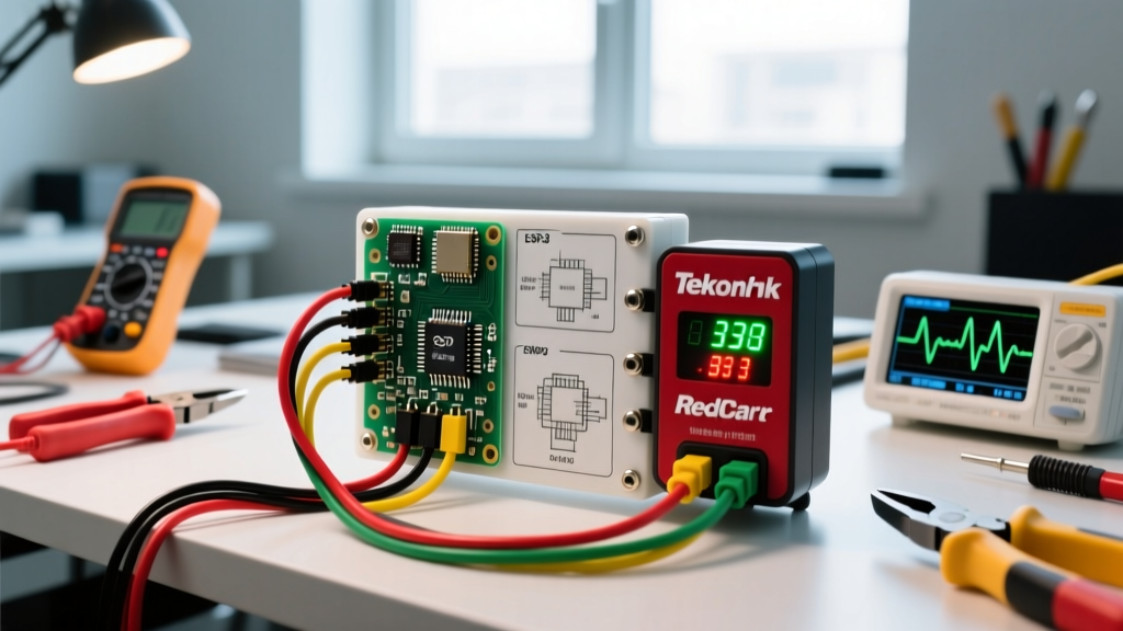
Before grabbing a multimeter, you must understand the standard 4-wire architecture that powers 95% of aftermarket and OEM-integrated brake controllers (such as the Tekonsha Prodigy P3, Redarc Tow-Pro Elite, and Curt Spectrum).
| Wire Color | Function | Recommended Gauge | Termination Point |
|---|---|---|---|
| White | Ground (-) | 10 AWG | Vehicle Chassis (Bare Metal) |
| Black | 12V Power (+) | 10 AWG | Battery Positive (via 30A Circuit Breaker) |
| Red | Stoplight Switch | 12 AWG | Brake Pedal Switch (Cold Side) |
| Blue | Brake Output | 10 AWG | 7-Way RV Blade (Pin 5) |
Step-by-Step Multimeter Diagnostics for Dead Controllers
If your controller display is completely blank, the issue is almost always on the power or ground side. Do not immediately assume the controller is dead. Follow this diagnostic sequence using a digital multimeter (DMM) like a Fluke 115 or Klein MM400.
- Test the 12V Supply: Set your DMM to DC Voltage. Place the red probe on the black wire at the back of the controller plug and the black probe on a known good chassis ground. You should read between 12.2V and 13.8V. If you read 0V, check the 30A inline circuit breaker near the battery and the main fuse in the vehicle's under-hood PDC (Power Distribution Center).
- Test the Ground Integrity: Move the red probe to the white wire and the black probe to the battery's negative terminal. With the controller plugged in, a reading above 0.1V indicates a high-resistance ground. Clean the chassis grounding point with 80-grit sandpaper and secure it with a star washer to bite through paint and rust.
- Verify the Stoplight Signal: Have an assistant press the brake pedal. Probe the red wire. You should see battery voltage (12V+) only when the pedal is depressed. If you have constant voltage, you have tapped the 'hot' side of the brake switch instead of the 'cold' side.
Translating Error Codes into Wiring Fixes
Modern proportional controllers feature microprocessors that monitor the blue brake output wire for anomalies. According to Tekonsha's official installation resources, interpreting these alphanumeric codes correctly will save you hours of guesswork.
Tekonsha Prodigy P2 / P3 Error Codes
- 'SH' (Short Circuit): The blue output wire is touching ground between the controller and the 7-way plug, or inside the trailer's umbilical cord. Inspect the 7-way plug for melted plastic or crossed pins. Use a tone generator to trace the blue wire under the dash for pinch points against the steering column.
- 'OL' (Overload): The controller is detecting a current draw exceeding its maximum threshold (typically 12-15 amps). This usually means a dead short inside one of the trailer's electric brake magnets, or the trailer wiring is undersized (e.g., using 14 AWG wire for a triple-axle trailer drawing 18 amps).
- 'NC' (No Connection): The controller cannot detect the trailer. This is rarely a controller fault; it is almost always a dirty 7-way plug, a severed blue wire at the trailer tongue jack, or corroded hub magnets.
Redarc Tow-Pro Elite LED Diagnostic Patterns
The Redarc Tow-Pro Elite uses a hidden LED knob that flashes specific colors to indicate wiring faults. For instance, two red flashes indicate a short circuit on the brake output wire, while three red flashes indicate an open circuit (broken wire or disconnected trailer). Because the Tow-Pro Elite mounts behind the dash, always test the wiring at the 7-way bumper plug first before pulling the dashboard apart.
Advanced Troubleshooting: Voltage Drop and the 7-Way RV Blade
A common, highly frustrating issue is a controller that works perfectly in the driveway but feels 'weak' or pulses erratically while driving. This is a classic symptom of voltage drop across the 7-way RV blade connector.
Pro Tip: Never rely on visual inspection for 7-way plugs. Copper oxidation can occur inside the female sockets of the truck-side receptacle, creating a high-resistance bottleneck that chokes amperage to the trailer brakes.
The Voltage Drop Test:
With the trailer connected and the manual override lever on the controller fully engaged, measure the DC voltage at the controller's blue wire. Then, measure the voltage at Pin 5 (the brake output pin) on the trailer-side plug. According to standards referenced by the RV Industry Association (RVIA), the voltage drop across the tow vehicle's wiring harness should not exceed 0.5V. If you measure 12.5V at the dash but only 10.8V at the bumper, your truck's factory wiring or the 7-way plug is degraded. Replace the truck-side receptacle with a heavy-duty pigtail (like the Hopkins Endurance 41145) and solder the connections rather than using crimp-only butt splices.
The 2026 Edge Case: LED Backfeed and Multiplexed Wiring
As of 2026, nearly all new travel trailers and fifth wheels utilize advanced LED lighting arrays and multiplexed wiring harnesses. This has introduced a new, poorly documented wiring anomaly: LED Backfeed.
Certain aftermarket and OEM LED trailer light drivers leak a small amount of voltage (1V to 3V) backward into the brake output circuit when the running lights are turned on. The brake controller's sensitive microprocessor detects this stray voltage and mistakenly assumes a trailer is connected, or worse, applies micro-braking force to the trailer while driving, leading to premature brake shoe wear and overheated hubs.
How to Diagnose and Fix LED Backfeed
- Isolate the Variable: Turn off the truck's headlights/running lights. If the controller's 'NC' code returns or the phantom braking stops, you have a backfeed issue.
- Install a Blocking Diode: Solder a 12V, 10-Amp blocking diode inline on the blue brake output wire, approximately 12 inches behind the 7-way plug. The diode's silver band must face toward the trailer. This allows current to flow to the brakes but blocks stray voltage from leaking back to the controller.
- Use a Load Resistor: Alternatively, installing a dedicated wiring resistor (such as the Curt 58200) between the brake output and ground will safely bleed off the phantom voltage. For more complex trailer wiring conversions, consult etrailer's comprehensive wiring FAQ for specific adapter harnesses.
Essential Troubleshooting Toolkit for the Road
Do not wait until you are stranded on the shoulder of an interstate to gather your diagnostic tools. Keep the following in your truck's glovebox or pass-through storage:
- Digital Multimeter: Must be capable of reading DC Voltage and Continuity.
- 7-Way Circuit Tester: A simple plug-in LED tester (e.g., Hopkins 80107) for quick visual pin verification.
- Dielectric Grease: Apply to all 7-way pins and ground ring terminals to prevent moisture intrusion and galvanic corrosion.
- Spare 30A Circuit Breaker & Fuses: Controllers draw minimal power at rest, but a seized brake magnet can instantly blow the main inline breaker.
- Heat-Shrink Butt Splices & Soldering Iron: Standard vinyl electrical tape will unravel in the heat of a truck bumper; always use adhesive-lined marine heat shrink for exterior wiring repairs.
By methodically isolating the power, ground, signal, and output circuits, you can resolve 99% of electric brake control wiring faults without replacing the controller itself. Remember that the controller is merely the brain; the wiring is the nervous system, and maintaining clean, high-gauge, corrosion-free connections is the key to safe, predictable towing.