
The Blueprint for Your Trailer Electrical Overhaul
When gutting a vintage Airstream, updating a horse trailer, or rebuilding a flatbed utility rig, the electrical phase is where most renovation budgets and timelines derail. Before you lay down new subflooring or spray closed-cell insulation, you must map out your DC and AC routing. Understanding how to read a wiring harness for trailer diagram is the critical first step in transitioning from a torn-down chassis to a fully functional, road-legal rig.
As of 2026, modern tow vehicles feature complex CAN-bus systems and sensitive trailer brake controllers. Feeding them incorrect signals or undersized wiring will trigger dashboard faults and compromise safety. This guide provides the exact specifications, wire gauges, and routing strategies required for a professional-grade trailer rewire.
Pre-Renovation Audit: Mapping the Chassis
Before ordering materials, perform a physical audit of the trailer frame. Older trailers often suffer from galvanic corrosion at the tongue and rear crossmembers. Your wiring harness cannot simply zip-tie to rusty steel.
- Identify Chassis Ground Points: Grind away paint and rust to bare metal at the tongue and rear bumper. These will serve as your primary ground bus locations.
- Plan Conduit Runs: Route wiring through the frame's C-channel or boxed tubing to protect against road debris. Avoid running wires over sharp axle brackets.
- Measure Exact Lengths: Add 18 inches of slack at the tongue for tight turning radiuses, and 12 inches at each wheel well for brake assemblies.
Decoding the Standard 7-Way RV Blade Pinout
The industry standard for campers and heavy utility trailers is the 7-way RV blade connector. When reviewing a wiring harness for trailer diagram for a 7-way system, you must adhere to the SAE J286 color-code standard to ensure compatibility with modern brake controllers and tow vehicle multiplexers. Refer to the SAE J286 Standard for exact compliance.
| Pin Position | Function | Standard Wire Color | Minimum AWG (Gauge) |
|---|---|---|---|
| Center (Ground) | Chassis Ground / White | White | 10 AWG |
| Pin 1 (Top Left) | Tail / Running Lights | Brown | 12 AWG |
| Pin 2 (Top Right) | Right Turn / Stop | Green | 12 AWG |
| Pin 3 (Bottom Right) | Left Turn / Stop | Yellow | 12 AWG |
| Pin 4 (Bottom Left) | Electric Brakes | Blue | 10 AWG |
| Pin 5 (Middle Left) | 12V Auxiliary / Charge | Black | 10 AWG |
| Pin 6 (Middle Right) | Reverse Lights / Aux | Purple | 12 AWG |
Wire Selection: Why Household Romex Will Fail
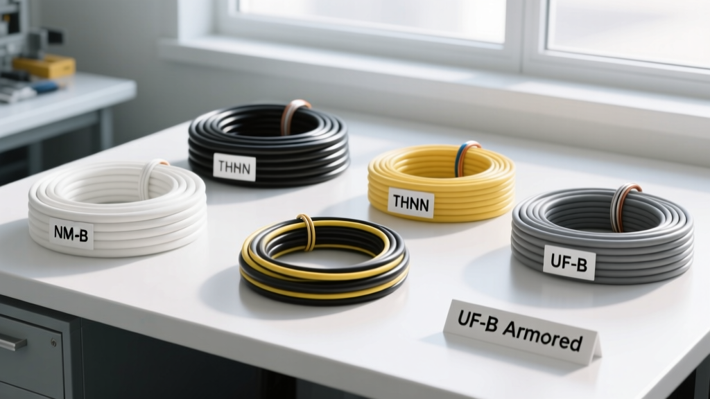
A catastrophic mistake in trailer renovations is using solid-core NM-B (Romex) wire intended for residential homes. Trailers experience high-frequency vibration and torsional flexing. Solid-core wire will work-harden, fracture, and short out inside the walls within a single season.
The Right Spec: SAE J1128 GXL
For all 12V DC chassis wiring, specify SAE J1128 GXL (Cross-Linked Polyethylene) stranded wire. GXL wire features a thin, high-temp insulation rated to 125°C (257°F), which is crucial when routing wires near wheel wells where brake heat radiates. For the main 12V feed from the tow vehicle to the trailer's breakaway battery and interior DC panel, use SGT (Battery Cable) or 6 AWG stranded copper to minimize voltage drop over the 25-foot run.
Calculating Voltage Drop for Brake Controllers
Electric trailer brakes require precise voltage to modulate correctly. If your wiring harness is undersized, the brake controller at the tow vehicle will read a 'Trailer Disconnected' or 'Overload' fault due to voltage drop. According to NFPA 1192 (Standard on Recreational Vehicles), voltage drop on critical safety circuits must not exceed 3%.
Expert Calculation: A standard dual-axle trailer draws roughly 12 Amps under heavy braking. Running 10 AWG copper wire (1.018 ohms per 1,000 ft) for a 25-foot one-way run (50 ft total circuit) results in a voltage drop of only 0.61V (approx 5%). To achieve the ideal 3% drop for high-performance disc brake conversions, upgrade the blue brake wire to 8 AWG.
Common Failure Modes in Trailer Rewires
During the planning phase, design your system to avoid these three prevalent edge cases:
- Grounding Through the Hitch Ball: Relying on the steel hitch ball for the ground circuit is a guaranteed failure point. Paint, rust, and grease act as resistors, causing tail lights to dim when brakes are applied (the 'ground loop' effect). Always run a dedicated 10 AWG white ground wire directly to the trailer frame.
- LED Conversion Backfeed: Upgrading to LED marker lights reduces amp draw, which can confuse older thermal flasher relays in the tow vehicle. If your tow vehicle is pre-2018, plan to install a CAN-bus adapter or load-resistor module near the 7-way plug.
- Corroded Bargman Connectors: Standard plastic 7-way plugs allow moisture ingress. In your renovation budget, allocate funds for a molded, sealed 7-way pigtail rather than a screw-terminal plug.
Essential Components for a 2026 Renovation
Sourcing commercial-grade components ensures your harness survives the elements. Integrate these specific items into your materials list:
- Epicord 7-Way Molded Trailer Plug (25ft Pigtail): Approx. $35. Features sealed injection-molded strain relief, eliminating the need for internal screw terminals that corrode.
- Curt 58240 7-Way Socket (Vehicle Side): Approx. $18. Features a stainless-steel spring-loaded flap and rubber gasket for UV and moisture resistance.
- Ancor Marine Grade Heat Shrink Butt Connectors: Approx. $18 per 50-pack. Contains polyamide hot-melt adhesive that melts at 250°F, creating a waterproof, vibration-proof seal. Never use standard vinyl crimps on a trailer.
- Adel Clamps (P-Clips) with EPDM Rubber Cushion: Use these every 14 inches to secure the harness to the frame, preventing the wire insulation from chafing against bare steel.
Frequently Asked Questions
Do I need a breakaway switch on a utility trailer?
Yes. Federal and state DOT regulations require a breakaway switch on any trailer equipped with electric brakes. During your renovation, wire the breakaway switch directly to a dedicated 12V 5Ah SLA (Sealed Lead Acid) or LiFePO4 battery mounted in a weatherproof box on the tongue, bypassing the main harness so it functions even if the 7-way plug is severed in an accident.
How do I test the harness before closing up the walls?
Before installing interior paneling or spray foam, connect the harness to a 12V DC power supply and a trailer brake tester. Use a digital multimeter to verify that the blue brake wire receives a full 12V under load, and use a thermal imaging camera to scan all crimp connections. Any connection glowing hotter than the ambient wire temperature indicates a high-resistance crimp that must be redone.