
The Bridge Between Schematic and Safe Installation
When tackling a home electrical remodel, staring at a schematic can feel like reading a foreign language. Understanding wiring electrical switches diagrams is the critical bridge between a successful DIY lighting upgrade and a dangerously miswired circuit. Whether you are replacing a cracked toggle in a 1970s ranch home or installing a whole-home smart lighting system, the diagram is your definitive roadmap. In this 2026 home project guide, we will decode the standard symbols, break down multi-way switch logic, and explore the physical execution required to match the paper plan to your junction box.
The Core Symbols in Switch Diagrams
Before connecting a single wire, you must recognize the universal nomenclature used in electrical schematics. Manufacturers like Leviton and Lutron standardize their wiring electrical switches diagrams using specific color codes and text labels:
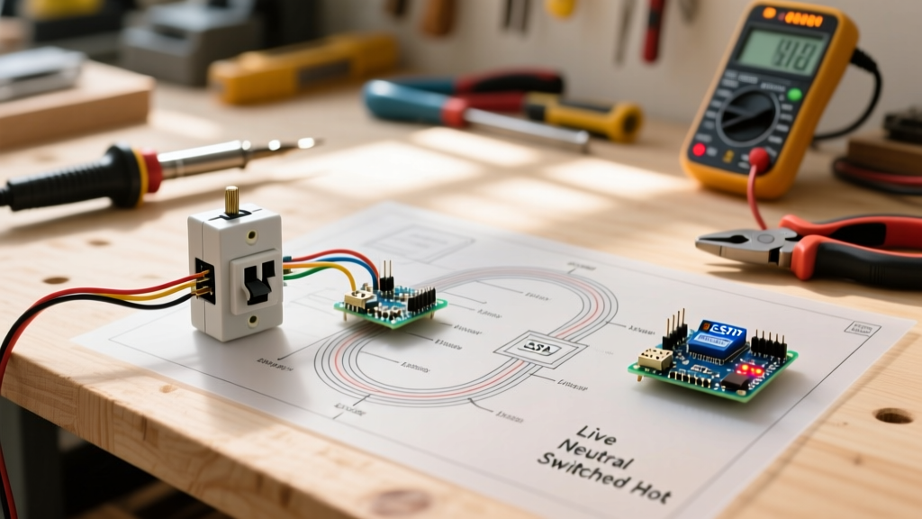
- Line (Hot): Usually represented by a black wire or a solid black line on the diagram. This is the unswitched 120V power coming directly from the breaker panel.
- Load (Switched Hot): Typically colored red or indicated by a dashed line. This wire carries power from the switch to the light fixture or receptacle only when the switch is closed.
- Neutral (Grounded Conductor): White wire or a light blue line on diagrams. It completes the circuit back to the panel. Historically absent in switch boxes, it is now a critical focus in modern diagrams.
- Ground (Equipment Grounding Conductor): Bare copper or green wire, depicted as a green line terminating at a grounding symbol (a vertical line with three descending horizontal bars).
Single-Pole vs. Multi-Way Switch Matrix
The complexity of wiring electrical switches diagrams scales with the number of control points you need for a single fixture. Below is a comparative matrix to help you identify which diagram matches your physical wall box.
| Switch Type | Terminal Count | Wire Count in Box | Primary Use Case | Avg. 2026 Cost (Standard) |
|---|---|---|---|---|
| Single-Pole (SPST) | 2 (plus ground) | 2 (Line, Load) | Standard bedroom or bathroom lighting controlled from one door. | $2.50 - $5.00 |
| 3-Way (SPDT) | 3 (plus ground) | 3 or 4 (Line, 2 Travelers, or Load + 2 Travelers) | Hallways or staircases controlled from two distinct locations. | $4.50 - $8.00 |
| 4-Way (DPDT) | 4 (plus ground) | 4 (2 pairs of Travelers) | Large rooms or long corridors requiring three or more control points. | $9.00 - $14.00 |
The 3-Way Switch Conundrum: Line, Load, and Travelers
The most frequent point of failure in DIY electrical projects is the 3-way switch. When reviewing wiring electrical switches diagrams for a 3-way setup, you will notice the absence of definitive "Line" and "Load" labels on the switch itself. Instead, you will see a Common terminal and two Traveler terminals.
Decoding the Physical Switch
Take the industry-standard Leviton Decora 5603 3-way switch as an example. The diagram will show:
- The Black Screw (Common): This is your anchor point. On the first switch in the circuit, the Line (hot) wire connects here. On the second switch, the Load (wire going to the light) connects here.
- The Brass Screws (Travelers): These two screws are interchangeable. They connect to the red and black wires of a 3-wire Romex (14/3 or 12/3) cable running between the two switch boxes. The diagram will show these crossing over, representing the internal toggle mechanism redirecting the current path.
- The Green Screw (Ground): Connects to the bare copper wire and the metal box (if applicable).
Pro-Tip for 3-Way Diagrams: Never rely on wire colors in an existing wall to match the diagram perfectly. Previous homeowners often used whatever wire was left in the spool. Always use a non-contact voltage tester and a multimeter to definitively identify the constant Line hot before mapping it to your diagram's Common terminal.
Smart Switch Diagrams and the NEC Neutral Mandate
The transition to smart home ecosystems has fundamentally altered wiring electrical switches diagrams. Traditional mechanical switches simply break the hot wire; they do not require power to operate. Smart switches, however, contain internal radios (Wi-Fi, Zigbee, or Lutron's Clear Connect) that require a constant trickle of 120V power to stay connected to your network.
The Neutral Wire Requirement
To power the internal radio without letting current leak through the LED bulb (which causes flickering), modern smart switches require a dedicated Neutral wire. This is explicitly detailed in diagrams for devices like the Lutron Caseta PD-6ANS (approx. $65) or the TP-Link Kasa KS200.
This aligns directly with the National Electrical Code. According to the NFPA's NEC Article 404.2(C), a neutral conductor is now strictly required at nearly all switch locations in new construction and major remodels. If your home was built before 2011, your switch boxes likely lack a neutral bundle. In this scenario, you must pivot your diagram to a "No-Neutral" smart switch (like the Lutron PD-5S-DV), which utilizes a bypass capacitor installed at the light fixture to complete the micro-current circuit.
From Paper to Punchout: Execution and Torque Specs
Reading wiring electrical switches diagrams is only half the battle; physical execution dictates the longevity and safety of the installation. Follow these precise physical parameters when translating the diagram to the junction box:
- Wire Stripping Length: Strip exactly 3/4-inch of insulation from 14 AWG or 12 AWG solid copper wire. Stripping too little results in insulation catching under the terminal screw (a high-resistance fire hazard). Stripping too much leaves exposed copper outside the terminal, risking a short against the ground wire.
- Connector Selection: Abandon traditional twist-on wire nuts for multi-wire neutrals in smart switch boxes. Use Wago 221-412 or 221-413 lever nuts (approx. $0.45 each). They provide a verifiable, vibration-proof connection and easily accommodate the pigtail wire included with smart switches.
- Terminal Torque: The NEC now mandates that terminal connections be tightened to the manufacturer's specified torque. For standard residential switches, this is typically between 12 and 14 in-lbs. Use an insulated torque screwdriver (like the Wiha 10163) to ensure the screw is tight enough to prevent arcing, but not so tight that it strips the brass threads or snaps the screw head.
Troubleshooting Common Diagram Misinterpretations
Even with a clear diagram, edge cases arise. Here is how to troubleshoot the most common physical deviations from the schematic:
1. The Smart Switch "Ghost" Power
The Symptom: You wired the smart switch exactly to the diagram, but the LED bulbs glow faintly when the switch is off, or the switch randomly reboots.
The Cause: You likely have a "switch loop" where the white wire in the wall is actually being used as a permanent hot (Line), not a neutral. Older wiring electrical switches diagrams often omitted the neutral entirely.
The Fix: Verify the white wire with a multimeter against the bare ground. If it reads 120V, it is a hot wire. You must cap it off and find a true neutral bundle in the back of the box, or switch to a no-neutral smart switch model.
2. The 3-Way Traveler Cross
The Symptom: The 3-way circuit only works when the other switch is in the "Up" position.
The Cause: The Line or Load wire was mistakenly placed on a brass Traveler screw instead of the black Common screw.
The Fix: Revisit the diagram. Identify the single wire that is hot (Line) or leads to the fixture (Load) and move it exclusively to the dark-colored Common screw.
Safety First: Verifying Your Work
Electrical work carries inherent risks. The U.S. Consumer Product Safety Commission (CPSC) strongly advises testing all circuits with a verified voltage tester before touching any bare wire, and ensuring all work complies with local municipal codes. Always pull the breaker and lock it out if you are working in a shared household. By meticulously following wiring electrical switches diagrams and respecting the physical realities of your junction box, you ensure a safe, code-compliant, and fully functional lighting upgrade.