
The Complexity Behind the Canopy: Reading a Wiring Electric Fan Diagram
Installing a ceiling fan seems like a straightforward weekend project until you open the canopy and stare at a tangle of black, white, blue, and green wires. Modern ceiling fans have evolved significantly from the simple single-motor units of the past. Today's models feature integrated LED light engines, DC motors with internal transformers, and wireless smart-home receivers. Consequently, interpreting a wiring electric fan diagram requires more than just matching wire colors; it demands an understanding of load balancing, neutral requirements, and National Electrical Code (NEC) compliance.
This guide provides a deep-dive analysis into the technical realities of ceiling fan wiring. We will break down when a homeowner can safely execute the installation using the manufacturer's diagram, and when the complexity of the electrical environment mandates a licensed electrician.
Decoding the Standard Wiring Electric Fan Diagram
Before deciding who should do the work, you must understand what the diagram is actually telling you. Most standard AC-motor ceiling fans (like the popular Hunter Dempsey or Hampton Bay Midili series) utilize a standardized color-coded harness emerging from the downrod:
- Black Wire: Hot line for the fan motor.
- Blue Wire: Hot line for the integrated light kit.
- White Wire: Neutral return (shared by both motor and light).
- Green/Bare Copper: Equipment grounding conductor.
The diagram will typically show two distinct wiring scenarios. Scenario A involves a wall setup with two separate hot wires (often a 3-wire Romex cable like 14/3 or 12/3), allowing independent wall control of the fan and light. Scenario B involves a single hot wire, requiring the black and blue wires to be pigtailed together, which forces the user to rely on the included pull chains or a remote-control receiver module hidden inside the canopy.
The DIY vs. Professional Decision Matrix
Not all installations carry the same risk profile. Use the matrix below to evaluate your specific scenario against the requirements of the wiring electric fan diagram you are holding.
| Installation Scenario | Diagram Complexity | DIY Feasibility | Professional Recommendation |
|---|---|---|---|
| Like-for-Like Swap (Existing fan-rated box, standard AC motor, no smart switches) | Low | High. Standard color-matching. | Not required unless physical mounting is compromised. |
| Smart Switch Retrofit (Adding Lutron Caseta or Leviton Decora smart fan controls) | Medium-High | Medium. Requires neutral wire verification in the wall box. | Recommended if wall box lacks a neutral or is overcrowded. |
| DC Motor Fan Installation (e.g., Minka-Aire, Modern Forms) | Medium | Low-Medium. Diagrams look simpler, but internal PCBs are highly sensitive to voltage spikes and incompatible dimmers. | Highly recommended if integrating with complex home automation panels. |
| New Location / Pan-to-Brace Conversion | High | Low. Requires attic access, structural bracing, and running new Romex. | Mandatory. Structural integrity and code compliance are critical. |
Critical NEC Code Requirements (2026 Perspective)
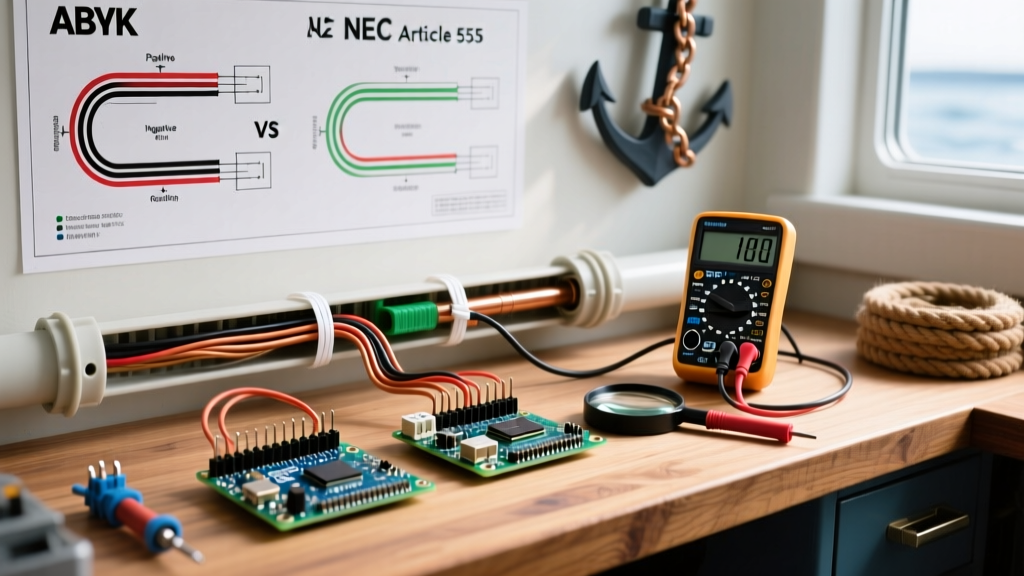
A wiring electric fan diagram only tells you how to connect the device; it does not tell you if your home's infrastructure is legally or safely capable of supporting it. The National Fire Protection Association (NFPA) updates the NEC regularly, and recent cycles have heavily targeted ceiling fan safety and smart device integration.
Junction Box Ratings (NEC Article 314.27)
The most common and dangerous DIY failure mode is mounting a heavy ceiling fan to a standard light fixture junction box. According to National Fire Protection Association (NFPA) guidelines under NEC Article 314.27, ceiling fan junction boxes must be specifically listed for fan support.
Expert Insight: If your fan weighs less than 35 lbs, a standard fan-rated plastic or metal box is sufficient. However, for fans exceeding 35 lbs (common with large-blade, flush-mount, or commercial-grade models), the box must be rated for 70 lbs and marked 'Acceptable for Fan Support of 70 lbs or Less.' If your current box is not rated, a professional must install an expandable Saf-T-Brace between the ceiling joists.
The Smart Switch Neutral Dilemma (NEC Article 404.2)
Modern smart fan controllers, such as the Lutron Caseta PD-FSQX fan speed controller, require a continuous neutral wire to power their internal radios. NEC Article 404.2 now mandates that a neutral conductor be present at almost all switch locations. If you live in a home built before 1985, your wall switch likely only has a 'switch loop' (a single 2-wire cable carrying hot and switched-hot). A DIYer attempting to wire a smart fan controller here will either fail to get the switch to boot or, worse, attempt to use the ground wire as a neutral—a severe shock and fire hazard that violates code.
Real-World Failure Modes & Edge Cases
When analyzing the gap between a successful DIY job and a professional callback, specific edge cases consistently emerge. Understanding these will help you read between the lines of your wiring electric fan diagram.
1. The 'Dimmer on a Motor' Fire Hazard
Many DIYers mistakenly wire a standard LED dimmer switch to the black fan motor wire, assuming it will control the fan speed. Standard dimmers use TRIACs to chop the AC sine wave. While this works for resistive lighting loads, it causes severe harmonic distortion in inductive fan motors. The result is a loud, aggressive humming, overheated windings, and eventual motor burnout. Professionals know to only use dedicated fan speed controls (like the Lutron FSQX) that utilize stepped voltage regulation or specialized microprocessors designed for inductive loads.
2. Frying the DC Motor Receiver
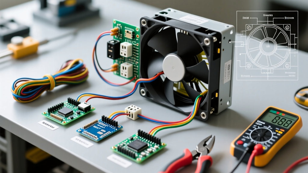
DC motor fans (which consume up to 70% less energy than AC models, as noted by EPA ENERGY STAR Ceiling Fan Guidelines) do not use the traditional black/blue wall wiring. Their diagrams show only Line, Neutral, and Ground connecting to a specialized canopy receiver. If a DIYer wires a DC fan through a wall-mounted variable speed control or a standard dimmer, the altered voltage will instantly destroy the fan's internal PCB transformer. Replacing a fried DC receiver board typically costs between $120 and $180, negating any DIY labor savings.
3. Overcrowded Canopies and Heat Dissipation
Modern smart home integrations often require stuffing a wireless receiver module (like the Bond Bridge or a proprietary Hunter SIMPLEconnect module) into the fan canopy alongside the wire nuts. If the DIYer uses oversized wire nuts or fails to dress the wires neatly, the canopy won't seat properly. More importantly, cramped spaces trap heat generated by the receiver and the motor capacitor, leading to premature component failure. Professionals use push-in wire connectors (like Wago Lever-Nuts) which reduce the physical volume of the splices by up to 40%, ensuring proper heat dissipation.
Cost Breakdown: DIY vs. Hiring an Electrician
To make an informed decision, you must weigh the financial risk. Below is a realistic 2026 cost analysis for a standard single-fan installation in an existing ceiling location.
| Cost Factor | DIY Installation | Professional Electrician |
|---|---|---|
| Labor | $0 (2-4 hours of your time) | $250 - $450 (Flat rate or hourly) |
| Materials (Wire nuts, connectors) | $10 - $15 | Included in labor/overhead |
| Smart Switch / Receiver | $60 - $120 | $75 - $150 (Plus markup) |
| Permit / Inspection (If required) | $50 - $100 | Usually pulled by electrician |
| Risk of Error (Motor/PCB damage) | High (Out of pocket replacement) | Zero (Covered by contractor liability) |
| Estimated Total (Excluding Fan Cost) | $70 - $235 | $325 - $600+ |
While the DIY route offers clear upfront savings, the U.S. Consumer Product Safety Commission (CPSC) regularly reports injuries related to improperly mounted ceiling fixtures falling. If your installation requires structural bracing, running new 14/3 Romex through finished drywall, or upgrading an outdated switch loop to include a neutral wire, the professional cost becomes a necessary investment in safety and code compliance.
Final Verdict: When to Put Down the Wire Strippers
Reading a wiring electric fan diagram is an excellent educational exercise, but it is only one piece of the installation puzzle. You can confidently proceed with a DIY installation if you are performing a like-for-like swap on a verified, fan-rated junction box, using standard wire nuts or Wago connectors, and sticking to basic AC motor models with pull-chain or remote control operation.
However, you should immediately pivot to hiring a licensed electrician if:
- Your ceiling box is plastic, unbraced, or not explicitly marked for fan support.
- You want to install smart wall controls but your switch box lacks a neutral wire.
- You are upgrading to a heavy DC-motor fan and need to ensure the circuit can handle the specific inrush current and smart-home integration requirements.
- You need to run new 3-wire cable to achieve independent wall control for the fan and light kit.
Electrical wiring is unforgiving of guesswork. When the diagram on the paper conflicts with the reality inside your junction box, always defer to the National Electrical Code and the expertise of a licensed professional.