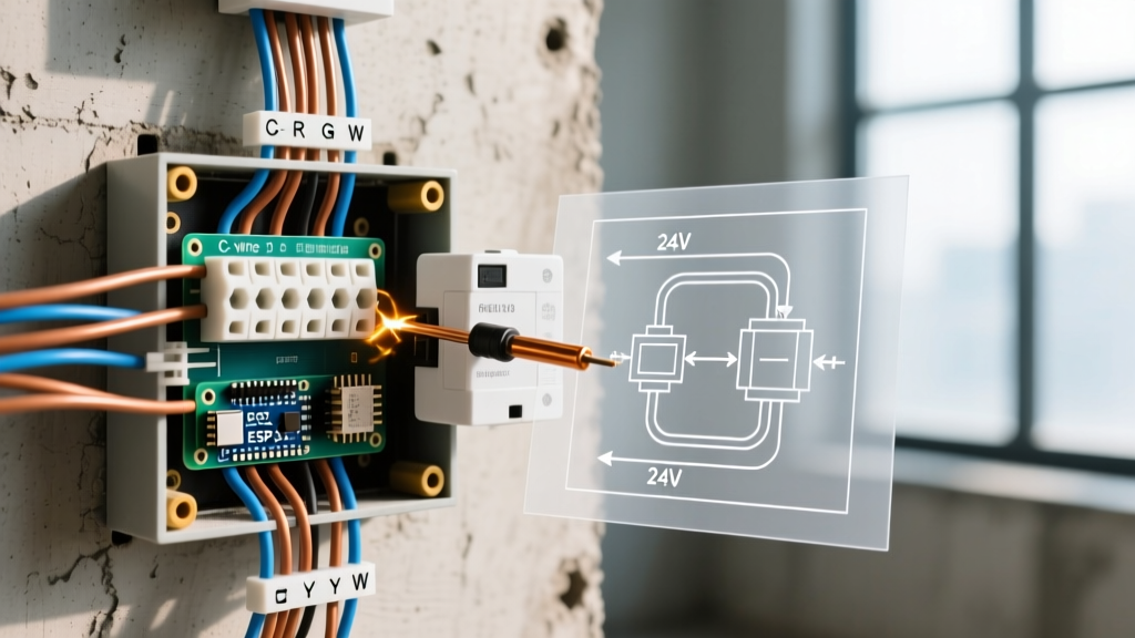

The Critical Role of Electric Fence Diagram Wiring in Troubleshooting
When an agricultural or security perimeter fails, guessing the source of the voltage drop is a waste of time and money. A properly designed electric fence diagram wiring schematic is your primary diagnostic map. In 2026, with the prevalence of high-output, low-impedance pulse energizers like the Gallagher M5800i (delivering up to 36 output joules), the electrical demands on the physical wiring infrastructure are immense. A minor flaw in your grounding matrix or a degraded polywire connection that might have gone unnoticed on a 2-joule system will severely cripple a modern high-tensile setup.
This troubleshooting guide moves beyond basic 'check the battery' advice. We will dissect the physical circuit, analyze failure modes using digital fault-finding tools, and provide actionable repair protocols based on standard wiring schematics.
⚠️ HIGH VOLTAGE SAFETY WARNING: Modern fence energizers produce peak DC pulses exceeding 10,000 volts. While the amperage is low and the pulse duration is measured in microseconds (typically 300μs), contacting a live high-tensile wire while standing in wet soil or touching a grounded structure can cause severe muscle spasms or secondary fall injuries. Always use a certified digital fence voltmeter and wear insulated gloves when performing terminal isolation tests.Decoding the Electric Fence Diagram Wiring Circuit
Before grabbing a fault finder, you must understand the complete circuit depicted in your electric fence diagram wiring layout. Unlike standard AC home wiring which relies on a neutral return wire to the transformer, an electric fence uses the earth itself as the return path. The circuit operates as follows:
- The Energizer: Converts grid or battery power into high-voltage DC pulses, pushing electrons out of the Live (Fence) terminal.
- The Live Wiring: High-tensile wire or polytape carries the pulse across the perimeter.
- The Animal/Target: Completes the circuit by touching the live wire while standing on the ground.
- The Earth Return: The pulse travels through the animal's body, into the soil, and toward the energizer's ground rods.
- The Grounding System: Galvanized ground rods collect the electrons and route them back up the Earth (Ground) wire to the energizer, completing the loop.
According to Penn State Extension, over 80% of all electric fence failures are directly tied to an inadequate grounding system failing to complete this final return loop. If your diagram shows three ground rods but the soil resistivity is high, the physical wiring on the ground side is your primary suspect.
Diagnostic Matrix: Symptom to Wiring Fault Isolation
Use the following matrix to cross-reference your voltmeter readings with specific nodes on your wiring diagram. You will need a peak-reading digital fence voltmeter (e.g., Gallagher or Zareba); standard AC/DC multimeters cannot accurately read the microsecond pulses of a modern energizer.
| Measured Voltage at Fence | Measured Voltage at Energizer Terminal | Probable Wiring Fault | Diagram Check Point |
|---|---|---|---|
| Low (< 3,000V) | High (8,000V+) | Line loss: vegetation contact, broken insulator, or poor splice. | Live wire routing, gate handles, corner insulators. |
| Low (< 3,000V) | Low (< 3,000V) | Energizer failure or severe grounding system short. | Earth terminal wire, ground rod clamps, rod spacing. |
| Fluctuating / Ticking | Stable | Arcing at a splice, loose crimp, or failing lightning diverter. | In-line strainers, lightning choke connections. |
| Zero (0V) | High | Complete physical break in the live wire or open gate switch. | Main feed line from energizer to perimeter, cutout switches. |
Deep Dive: Grounding System Failures (The #1 Culprit)
If your electric fence diagram wiring specifies a grounding array, you must verify it meets the demands of your specific energizer output. The industry standard 'Rule of Thumb' is a minimum of three feet of ground rod per output joule. For a 36-joule energizer, you theoretically need 108 feet of ground rod. In practical 2026 installations, this is achieved using multiple 6-foot or 8-foot hot-dipped galvanized steel rods driven deep into permanently moist soil.
Critical Wiring Mistakes in the Ground Array
- Galvanic Corrosion via Mixed Metals: Never mix copper-clad ground rods with galvanized steel wire or clamps. The electrolytic reaction will rapidly corrode the steel, creating a high-resistance barrier that blocks the pulse return. Always use hot-dipped galvanized steel rods with galvanized clamps and wire.
- Insufficient Spacing: Ground rods must be spaced at least 10 feet apart. Placing them too close together causes them to share the same soil volume, effectively acting as a single rod and failing to lower the overall ground resistance.
- Using Aluminum for Ground Leads: While aluminum wire is cheap and highly conductive for the live fence, it corrodes almost instantly when buried or exposed to the constant moisture around ground rods. Your diagram must specify 12.5-gauge galvanized steel or approved ground lead cable for all earth-side connections.
For comprehensive regional guidelines on soil resistivity and grounding requirements, the Ontario Ministry of Agriculture, Food and Rural Affairs provides excellent schematics for adapting ground arrays to high-resistance soils, including the use of 'ground-enhancing' bentonite clay backfills.
Diagnosing Wire and Insulator Shorts on the Live Side
When the energizer terminal reads a healthy 9,000V but the end of a 2-mile perimeter reads only 2,500V, your wiring diagram indicates a line loss issue. High-tensile 12.5-gauge wire has very low inherent resistance; therefore, the voltage drop is almost certainly caused by leakage to the ground.
The 'Divide and Conquer' Fault Finding Method
Rather than walking the entire perimeter with a digital fault finder, use your wiring diagram to identify midpoint cutout switches or gate handles.
- Isolate the Halves: Open the switch at the exact midpoint of the fence line. Check the voltage at the switch. If it jumps back to 8,000V+, the fault is in the second half of the circuit.
- Deploy the Fault Finder: Walk toward the faulty half. A digital fault finder (like the Gallagher Fault Finder) measures the magnetic field generated by the pulse. The arrows will point in the direction of the current flow. When you pass the short circuit, the arrows will reverse direction or drop to zero.
- Inspect High-Risk Nodes: Focus on corners where wire tension can pull posts inward, causing the wire to touch wooden braces. Check gate handles where the metal hook may be arcing against the wooden post.
Expert Insight: In early spring or after heavy rains, fast-growing broadleaf weeds and vines can drape over the bottom wire, creating thousands of micro-shorts. This 'vegetation loading' can drain a 10-joule energizer. If your diagram wiring allows, consider converting the bottom wire to a ground wire (alternating hot/ground configuration) in areas with severe weed pressure. This ensures the animal completes the circuit directly upon contact, bypassing the need for soil conductivity.
Energizer Output vs. Line Loss: Material Considerations
The physical materials specified in your electric fence diagram wiring directly impact how far the pulse can travel before degrading below the 4,000V minimum required for cattle and sheep control (or 7,000V for predator/wildlife exclusion).
| Wiring Material | Resistance per 1,000 ft | Max Effective Distance | Best Application |
|---|---|---|---|
| 12.5-ga High-Tensile Steel | ~ 3.5 Ohms | Up to 20+ miles | Permanent perimeter fencing, high-output energizers. |
| 14-ga Galvanized Steel | ~ 5.8 Ohms | Up to 10 miles | Standard paddocks, medium-duty setups. |
| 9-Strand Polywire (Turbo) | ~ 30 Ohms | Up to 1 mile | Temporary rotational grazing, strip grazing. |
| Standard Polytape (1/2 inch) | ~ 150+ Ohms | Under 500 feet | Horse visibility, very short enclosures. |
If your wiring diagram specifies polywire for a 3-mile perimeter, the design itself is flawed. The stainless steel or tinned copper filaments woven into polywire have high resistance. To troubleshoot low voltage at the end of a polywire run, the only permanent fix is to upgrade the main feed lines to 12.5-gauge high-tensile wire and use the polywire only for the final cross-fencing drop lines.
Frequently Asked Questions (FAQ)
Why does my fence click but the voltmeter reads zero?
The clicking sound is the internal capacitor discharging inside the energizer. If the voltmeter reads zero on the fence wire, you have a complete break in the live circuit immediately after the terminal, or your cutout switch is turned off. Check the physical connection at the energizer's live terminal; the set screw may have vibrated loose, or the wire may have snapped at the first strain insulator.
Can I use my home's copper grounding rod for my electric fence?
No. Your electric fence diagram wiring must show a completely independent grounding system, located at least 30 feet away from your home's utility ground, telephone grounds, or metal water pipes. Connecting the fence ground to the utility ground can introduce high-voltage pulses into your home's electrical system, potentially damaging sensitive electronics and creating a severe shock hazard inside the building.
How do I test if the energizer itself is failing?
Perform an Isolation Test. Turn off the energizer and disconnect both the live fence wire and the ground wire from the terminals. Turn the unit back on. Use a specialized fence voltmeter to measure directly across the two bare terminals (or use a short piece of heavily insulated wire to create a 1/4-inch spark gap). If the unit reads its maximum rated voltage (e.g., 10,000V) across the bare terminals, the energizer is perfectly healthy, and the fault lies 100% in your external wiring or grounding array.