
Understanding NEC Article 625 for EVSE Installations
Installing an Electric Vehicle Supply Equipment (EVSE) system is one of the most demanding residential electrical projects you can undertake. Unlike standard appliance circuits, electric car charger wiring involves high continuous loads that generate significant heat over extended periods. According to the National Electrical Code (NEC) Article 625, any EVSE installation must adhere to strict guidelines regarding overcurrent protection, wire ampacity, and physical routing. As local jurisdictions continue to adopt and enforce the latest NEC standards into 2026, electrical inspectors are scrutinizing EV installations more closely than ever. Failing an inspection not only delays your ability to charge your vehicle but can also result in costly tear-downs and rewiring. This guide breaks down the exact compliance metrics inspectors use to evaluate electric car charger wiring.
Load Calculations: The #1 Reason for Inspection Failure
Before pulling a single foot of wire, you must perform a service load calculation under NEC Article 220. Many homeowners assume a 200-amp service panel can easily handle a new EV charger. However, a 200-amp panel only provides 160 amps of continuous capacity (applying the 80% rule). If your home's existing baseline continuous load—factoring in HVAC, electric ranges, dryers, and general lighting—calculates to 130 amps, you only have 30 amps of headroom.
The Continuous Load Formula:
EVSE Maximum Output (Amps) × 1.25 = Minimum Required Branch Circuit Rating.
Example: A 48-amp Tesla Wall Connector requires a 60-amp breaker (48 × 1.25 = 60).
If adding that 60-amp breaker pushes your total calculated load beyond your service panel's rated capacity, the inspector will red-tag the installation. In these cases, you must either upgrade your main service (a $3,000 to $5,000 investment) or install an Energy Management System (EMS) that dynamically throttles the charger's amperage based on the home's real-time power consumption.
Wire Sizing and Breaker Selection Matrix
Choosing the correct wire gauge is critical for preventing voltage drop and thermal degradation. Inspectors will check the wire gauge against the breaker size and the specific insulation type. Below is the standard compliance matrix for copper and aluminum conductors in residential EVSE wiring.
| EVSE Max Output | Required Breaker | Copper Wire (THHN in Conduit) | Aluminum Wire (XHHW/SER) |
|---|---|---|---|
| 16 Amps | 20 Amp | 12 AWG | 10 AWG |
| 32 Amps | 40 Amp | 8 AWG | 6 AWG |
| 40 Amps | 50 Amp | 6 AWG | 4 AWG |
| 48 Amps | 60 Amp | 6 AWG (or 4 AWG for long runs) | 2 AWG |
Pro Tip: For runs exceeding 75 feet, inspectors highly recommend upsizing the wire by one gauge to mitigate voltage drop, which should ideally remain below 3% for branch circuits according to Alternative Fuels Data Center guidelines.
The GFCI Trap: Receptacle vs. Hardwired Compliance
One of the most common inspection failure modes involves Ground Fault Circuit Interrupter (GFCI) protection. Under NEC 625.54, if you install a NEMA 14-50 receptacle to plug in a portable EV charger, the branch circuit must have GFCI protection. This requires a specialized 50-amp GFCI breaker, which can cost upwards of $150.
However, if you hardwire a stationary EVSE (like the ChargePoint Home Flex or Tesla Wall Connector), the unit's internal Ground Fault Protection Equipment (GFPE) satisfies the code. In this scenario, a standard thermal-magnetic breaker is not only permitted but preferred. Many inexperienced electricians unnecessarily install a GFCI breaker on a hardwired circuit, leading to overlapping protection thresholds and nuisance tripping. Inspectors will note this as a code violation under NEC 110.3(B) regarding equipment listing and labeling instructions.
Physical Routing and Working Clearances
How you route the wiring to the charging location is just as important as the wire itself. Inspectors evaluate physical routing based on several key metrics:
- Conduit Fill and Bend Radius: If using THHN wires in PVC or EMT conduit, you must adhere to NEC Chapter 9, Table 1 for conduit fill percentages. Exceeding 40% fill makes wire pulling difficult and damages insulation. Furthermore, you cannot exceed 360 degrees of total bends between pull points.
- Underground Burial Depths: For detached garages or outdoor pedestals, PVC conduit must be buried at a minimum depth of 18 inches, while rigid metal conduit (RMC) requires 6 inches of cover. Direct burial cables (like UF-B) require 24 inches of depth.
- Working Space (NEC 110.26): The area in front of the EVSE disconnect or panel must maintain a clear working space of at least 30 inches wide, 36 inches deep, and 6.5 feet high. Inspectors will fail an install if the charger is mounted in a tight corner where a technician cannot safely open the enclosure door 90 degrees.
Torque Specifications and Mechanical Execution
As of recent code cycles, inspectors are strictly enforcing NEC 110.14(D), which mandates that all lug terminations be torqued to the manufacturer's specified values. For a standard Square D QO 60A breaker, the lug torque is typically 45 in-lbs.
To pass inspection without the inspector needing to bring their own testing tools, use a calibrated torque screwdriver (such as the Klein Tools 705/8) to tighten the lugs, and immediately apply a streak of torque seal (inspection lacquer) across the screw and lug. This visual indicator proves to the inspector that the termination was performed to exact specifications, satisfying both NEC 110.14(D) and NEC 110.12 (Mechanical Execution of Work).
Subpanel Edge Cases: Grounding vs. Neutral Bonding
When running a feeder to a detached garage subpanel specifically for electric car charger wiring, you must adhere to NEC 250.32. This requires a 4-wire feed (two hots, one neutral, one equipment ground). Inside the detached subpanel, the neutral bus bar and the ground bus bar must remain completely isolated. Bonding them together in a subpanel creates a parallel neutral path, which is an instant red-tag failure and a severe shock hazard.
Additionally, the detached structure requires its own grounding electrode system. You must install two 8-foot copper ground rods, spaced at least 6 feet apart, bonded to the subpanel's ground bus with a continuous 6 AWG bare copper grounding electrode conductor. Omitting the ground rods is a frequent oversight that inspectors actively look for in 2026 EVSE additions.
Final Inspection Preparation Checklist
Before calling your local authority having jurisdiction (AHJ) for the final rough and trim inspections, verify the following:
- Load calculation spreadsheet is printed and attached to the inside of the panel door.
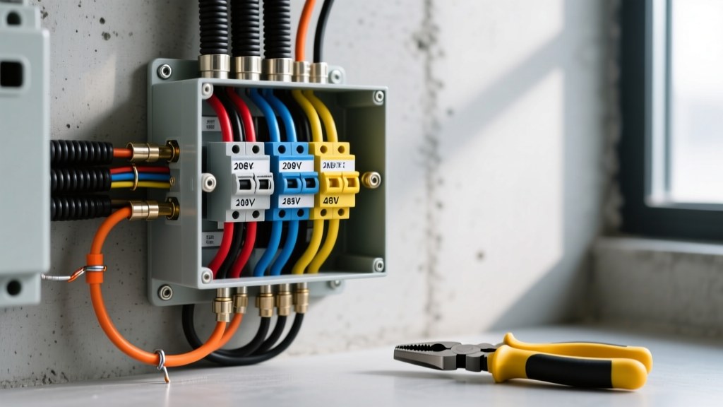
- All conductors are neatly dressed, zip-tied, and labeled with circuit identification.
- Torque seal is visibly applied to all breaker and busbar lug terminations.
- The EVSE enclosure is mounted securely to structural studs or masonry, not just drywall anchors.
- GFCI protection is correctly applied (breaker for receptacles, internal GFPE for hardwired).
By treating electric car charger wiring as a high-performance, continuous-duty circuit rather than a standard appliance hookup, you ensure a safe, code-compliant installation that will pass inspection on the first visit and reliably charge your vehicle for years to come.