
Decoding Emergency Electrical Wiring for Residential Backup
When the grid fails, the difference between a minor inconvenience and a catastrophic loss of property often comes down to your home's backup power infrastructure. Emergency electrical wiring in a residential setting is not simply about running an extension cord to a portable generator; it is a highly regulated, precision-engineered system designed to isolate utility power, protect linemen, and safely distribute electricity to critical circuits. As of the 2026 adoption cycle of the 2023 National Electrical Code (NEC), local inspectors are cracking down on improper standby wiring, making it imperative to understand the exact requirements for critical load panels and transfer equipment.
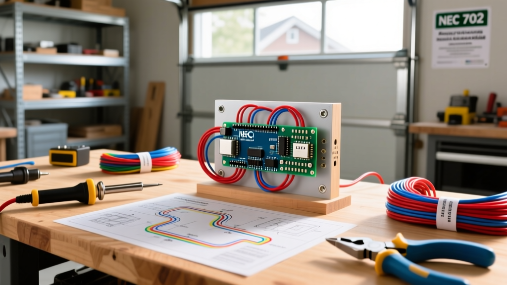
Unlike commercial buildings that require NEC Article 700 (Emergency Systems) for life-safety egress lighting, residential backup power typically falls under NEC Article 702 (Optional Standby Systems). This article dictates the rules for transfer equipment, grounding, and load management when utility power is replaced by a portable generator, whole-house standby unit, or solar-battery array.
Transfer Switches vs. Interlock Kits: Choosing Your Isolation Method
The cornerstone of safe emergency electrical wiring is preventing "backfeeding"—the lethal condition where generator power travels backward through the main breaker and out to the utility transformer, potentially electrocuting utility workers. You have two primary code-compliant paths to achieve isolation:
1. Manual Transfer Switches (MTS)
A dedicated MTS, such as the Reliance Controls Pro/Tran2 (Model 31410CRK), routes specific branch circuits from your main panel into a secondary enclosure. This is ideal for targeted emergency wiring where you only need to power 6 to 10 essential circuits (refrigerator, well pump, furnace blower, and a few receptacles). Pricing for a high-quality 30-amp, 10-circuit MTS ranges from $400 to $550, excluding installation labor and copper.
2. Generator Interlock Kits
An interlock kit (e.g., Siemens ECSBPK01 or SquareD HOMCGK2C) is a mechanical sliding plate installed on your existing main breaker panel. It physically prevents the main utility breaker and the generator backfeed breaker from being turned on simultaneously. This approach costs significantly less ($65 to $120 for the hardware) and allows you to select any circuit in your main panel to power, provided you do not exceed the generator's total wattage. The trade-off? It relies entirely on user discipline to manage loads and avoid tripping the generator's main breaker.
| Feature | Manual Transfer Switch (MTS) | Mechanical Interlock Kit |
|---|---|---|
| Hardware Cost | $400 - $800 | $65 - $120 |
| Circuit Selection | Pre-wired (6 to 16 circuits) | Any circuit in main panel |
| Load Management | >Excellent (Wattmeters often included)Poor (Requires manual calculation) | |
| Installation Time | 4 - 6 hours | 1 - 2 hours |
| Neutral Switching | Available (Switched Neutral models) | Not applicable |
Calculating Critical Loads and Wire Sizing
Before pulling a single foot of wire, you must calculate your emergency loads to size your generator inlet box and feeder cables correctly. Undersized emergency electrical wiring will cause severe voltage drop, potentially destroying the control boards on modern HVAC systems and smart refrigerators.
| Appliance / Load | Running Watts | Starting (Surge) Watts | Breaker Size | Min. Wire Gauge (THHN/SER) |
|---|---|---|---|---|
| Refrigerator (Standard) | 700W | 2,200W | 15A / 120V | 14 AWG |
| Submersible Well Pump (1/2 HP) | 1,000W | 3,000W | 20A / 240V | 12 AWG |
| Gas Furnace Blower Motor | 800W | 2,300W | 15A / 120V | 14 AWG |
| Electric Water Heater (4500W) | 4,500W | 4,500W | 30A / 240V | 10 AWG |
| Whole Home Transfer Feeder | 12,000W | N/A | 50A / 240V | 6 AWG (SER Cable) |
Step-by-Step: Wiring a 50-Amp Generator Inlet and Transfer Switch
For a robust home project guide, we will outline the installation of a 50-Amp emergency wiring setup using a Generac 6376 50-Amp Power Inlet Box and a corresponding 50-Amp MTS. This setup supports up to 12,000 running watts, covering most mid-sized homes' critical needs.
Step 1: Mounting the Inlet Box and Clearances
Mount the inlet box on the exterior of the home, ideally within 3 feet of the main electrical panel to minimize voltage drop and copper costs. According to the U.S. Consumer Product Safety Commission (CPSC), portable generators must never be operated near open windows or doors. While the inlet box itself doesn't emit gas, routing the generator cord safely requires placing the inlet box on a wall where the generator can sit at least 20 feet away from the home, as recommended by Ready.gov and modern safety standards.
Step 2: Pulling the Feeder Cable
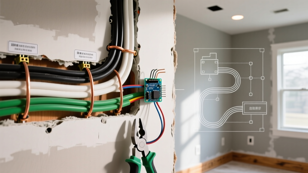
For a 50-amp circuit, use 6-3 SER (Service Entrance Round) copper cable if running through finished walls, or individual 6 AWG THHN wires pulled through 3/4-inch PVC or EMT conduit.
- Pro Tip: When stripping SER cable, use a dedicated cable ripper (like the Klein Tools 11055) to avoid nicking the inner THHN insulation. A nicked neutral wire on a 240V multi-wire branch circuit can cause a catastrophic overvoltage condition, sending 240V down a 120V leg and frying electronics.
Step 3: Terminating and Torquing Lugs
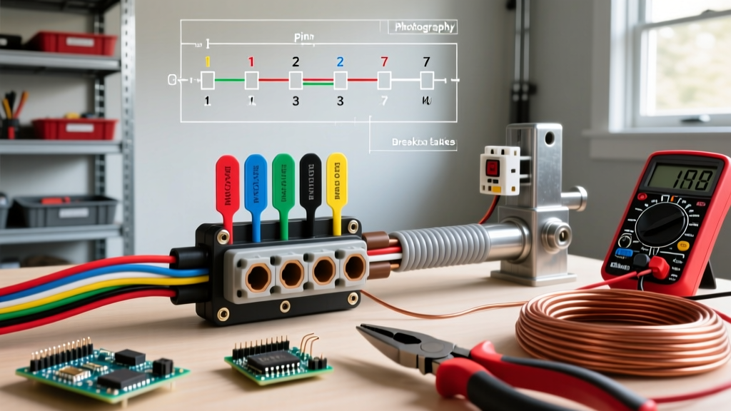
Connect the two hot legs (Black and Red) to the 50A breaker feeding the transfer switch. Connect the White neutral to the isolated neutral bus bar in the MTS, and the bare Copper ground to the grounding bus bar.
Critical E-E-A-T Warning: The 2023 NEC (and subsequent 2026 local adoptions) strictly enforces torque specifications for terminal lugs. Use a calibrated torque screwdriver (e.g., Wiha 2850-01) set to the manufacturer's specification—typically 45 in-lbs for 6 AWG copper on standard Square D or Eaton breakers. Hand-tightening leads to thermal expansion/contraction cycles that loosen the lug over time, resulting in arcing and panel fires.
Common Failure Modes and Edge Cases in Emergency Wiring
Even experienced DIYers make critical errors when configuring emergency electrical wiring. Watch out for these specific failure modes:
The Neutral Bonding Conflict
Most portable generators under 10kW feature a "bonded neutral," meaning the neutral wire is physically connected to the generator's metal frame (ground). If your home's main panel also has a bonded neutral (which it should), connecting the generator via a standard transfer switch that does not switch the neutral creates a parallel path for neutral current to flow on the grounding wires. This causes ground loops, nuisance GFCI tripping, and potential shock hazards. The Fix: Either purchase a "Switched Neutral" transfer switch (which breaks the neutral connection along with the hots) or have a qualified technician "float" the neutral on the portable generator by removing the internal bonding jumper.
Overloading the Inlet Box Prongs
A common mistake is pairing a 50-amp generator inlet box with a 60-amp breaker in the main panel. The breaker must never exceed the amperage rating of the inlet box or the generator cord. If you use a 50A inlet (NEMA 14-50), the backfeed breaker in the main panel must be 50A or less, protecting the physical prongs of the inlet from melting during a sustained overload.
Frequently Asked Questions
Can I use aluminum wire for my emergency generator feeder?
Yes, but you must upsize the wire. Aluminum has a lower ampacity than copper. For a 50-amp emergency feeder, you must use 4-2-4-2 Aluminum SER cable instead of 6-3 Copper SER. Furthermore, you must apply an anti-oxidant compound (like Noalox) to the aluminum strands before terminating them in the lugs to prevent galvanic corrosion and high-resistance connections over time.
Does a solar battery backup require the same wiring as a gas generator?
While the isolation principles (preventing backfeed) are identical, solar-battery systems like the Tesla Powerwall or Enphase IQ require specialized AC-coupled or DC-coupled transfer mechanisms that comply with NEC Article 705 (Interconnected Electric Power Production Sources). The wiring must account for continuous duty ratings, meaning conductors must be sized at 125% of the inverter's maximum continuous output current.